


Quick Research
Generate reliable direction feasibility study reports for your R&D in just a few steps.

Technical Q&A
Discover and master advanced knowledge NOW. Basics, ideas, possibilities, all at once.

Find Solutions
As an expert in R&D theories, this can generate solutions to your technical problems instantly.

Evaluate Feasibility
Analyze your overall solution with one click, know your potential R&D risks in advance.

Monitor Landscape
Get weekly tech updates, stay abreast of the latest tech innovations and key insights.
Auxiliary braking device for magnetic rheological body petroleum drilling rig
An auxiliary brake and variant technology, applied in mechanical equipment, hydraulic resistance brakes, brake types, etc., can solve the problems of not easy to dissipate heat, rapid temperature rise, high manufacturing precision, and overcome the problems of poor low-speed performance, large amount of winding, and high manufacturing low cost effect
- Summary
- Abstract
- Description
- Claims
- Application Information
AI Technical Summary
Problems solved by technology
Method used
Image

Examples
Embodiment 1
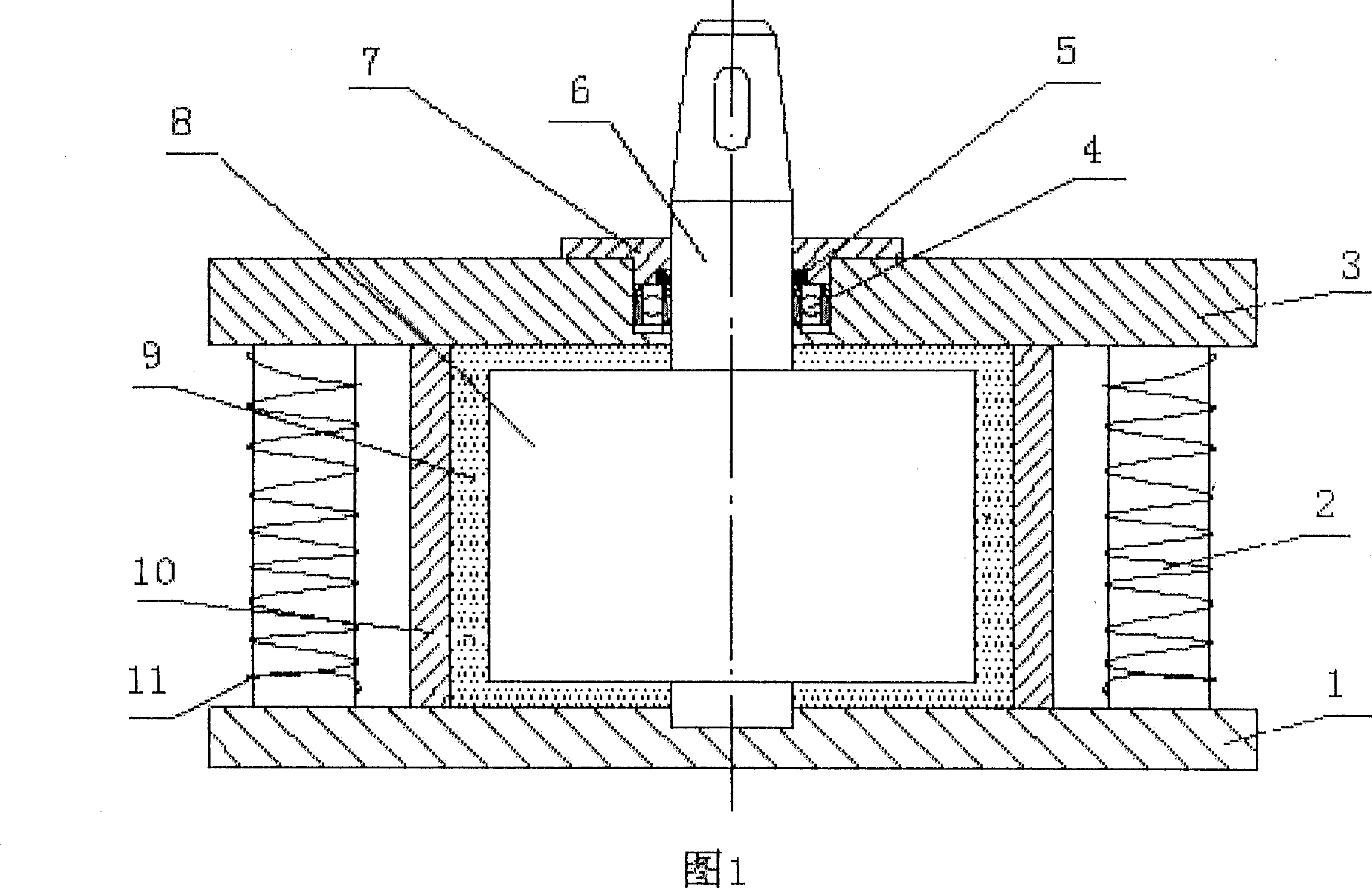
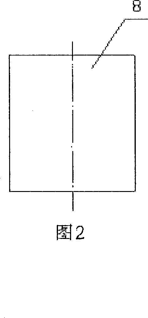
[0029] Embodiment 1: refer to accompanying drawing 1. Magneto-rheological fluid oil drilling rig auxiliary braking device, the upper and lower magnetic end caps 1 and 3 have an outer diameter of 1000 mm and a thickness of 50 mm, and are made of magnetic material. There is a shaft hole in the middle of the upper magnetic end cover 3 . A cylindrical cylinder 10 made of a non-magnetic material is fixed between the upper and lower magnetic end caps 1 and 3. The cylindrical cylinder 10 has an inner diameter of 700 mm and a height of 300 mm and is made of a non-magnetic material. There are two magnetically conductive cylinders 2 that are wound with excitation coils outside the cylindrical cylinder 10, the effective length of the magnetically conductive cylinders 2 being wound with excitation coils is 300 millimeters, and the diameter is 70 millimeters. Two magnetically conductive cylinders 2 wound with excitation coils are installed on both sides of the cylinder 10; There is non-m...
Embodiment 2
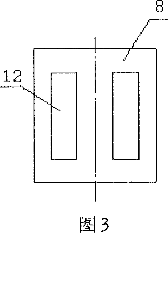
[0031] Embodiment 2: Embodiment 2 is basically the same as Embodiment 1, the difference is that the number of magnetically permeable cylinders 2 wound with excitation coils is four, and the magnetically permeable cylinders 2 wound with excitation coils are evenly distributed on the outside of cylinder 10 . The number of turns of the exciting coil 11 on the magnetically permeable cylinder 2 wound with the exciting coil is 350 turns respectively. Refer to accompanying drawing 3. The number of blades 8 can be four. The shape of the blade 8 is an empty slot type, and there are two symmetrical rectangular holes 12 on the blade 8 . The gap between the side end surface and the upper and lower end surfaces of the blade 8 and the cylinder barrel 10 and the upper and lower magnetic end caps 1 and 3 respectively is 3 millimeters.
Embodiment 3
[0032] Embodiment 3: Embodiment 2 is basically the same as Embodiment 1, the difference is that the number of magnetically conductive cylinders 2 wound with excitation coils is 6, and the magnetically conductive cylinders 2 wound with excitation coils are evenly distributed on the outside of cylinder 10 . The number of turns of the exciting coil 11 on the magnetically permeable cylinder 2 wound with the exciting coil is 750 turns respectively. Refer to accompanying drawing 4. The number of blades 8 can be 2 pieces. The shape of the blade 8 is an open type, and a cylinder 13 with a tapered hole is arranged on both sides of the blade 8 . The gap between the side end surface and the upper and lower end surfaces of the blade 8 and the cylinder barrel 10 and the upper and lower magnetic end caps 1 and 3 respectively is 6 millimeters.
PUM
| Property | Measurement | Unit |
|---|---|---|
| The inside diameter of | aaaaa | aaaaa |
| Diameter | aaaaa | aaaaa |
Abstract
Description
Claims
Application Information
 - R&D Engineer
- R&D Manager
- IP Professional
- Industry Leading Data Capabilities
- Powerful AI technology
- Patent DNA Extraction
Browse by: Latest US Patents, China's latest patents, Technical Efficacy Thesaurus, Application Domain, Technology Topic, Popular Technical Reports.
© 2024 PatSnap. All rights reserved.Legal|Privacy policy|Modern Slavery Act Transparency Statement|Sitemap|About US| Contact US: help@patsnap.com