


Quick Research
Generate reliable direction feasibility study reports for your R&D in just a few steps.

Technical Q&A
Discover and master advanced knowledge NOW. Basics, ideas, possibilities, all at once.

Find Solutions
As an expert in R&D theories, this can generate solutions to your technical problems instantly.

Evaluate Feasibility
Analyze your overall solution with one click, know your potential R&D risks in advance.

Monitor Landscape
Get weekly tech updates, stay abreast of the latest tech innovations and key insights.
Device for recovering solvent in wind cooling type dry washing machine
The technology of a solvent recovery device and a cooling recovery device is applied in the field of washing machinery, and can solve the problems of large difference in the heat content of the solvent, low thermal efficiency, complex structure, etc., and achieve the effects of convenient and reliable use, reduced operating costs, and simplified structure.
- Summary
- Abstract
- Description
- Claims
- Application Information
AI Technical Summary
Problems solved by technology
Method used
Image

Examples
Embodiment 1
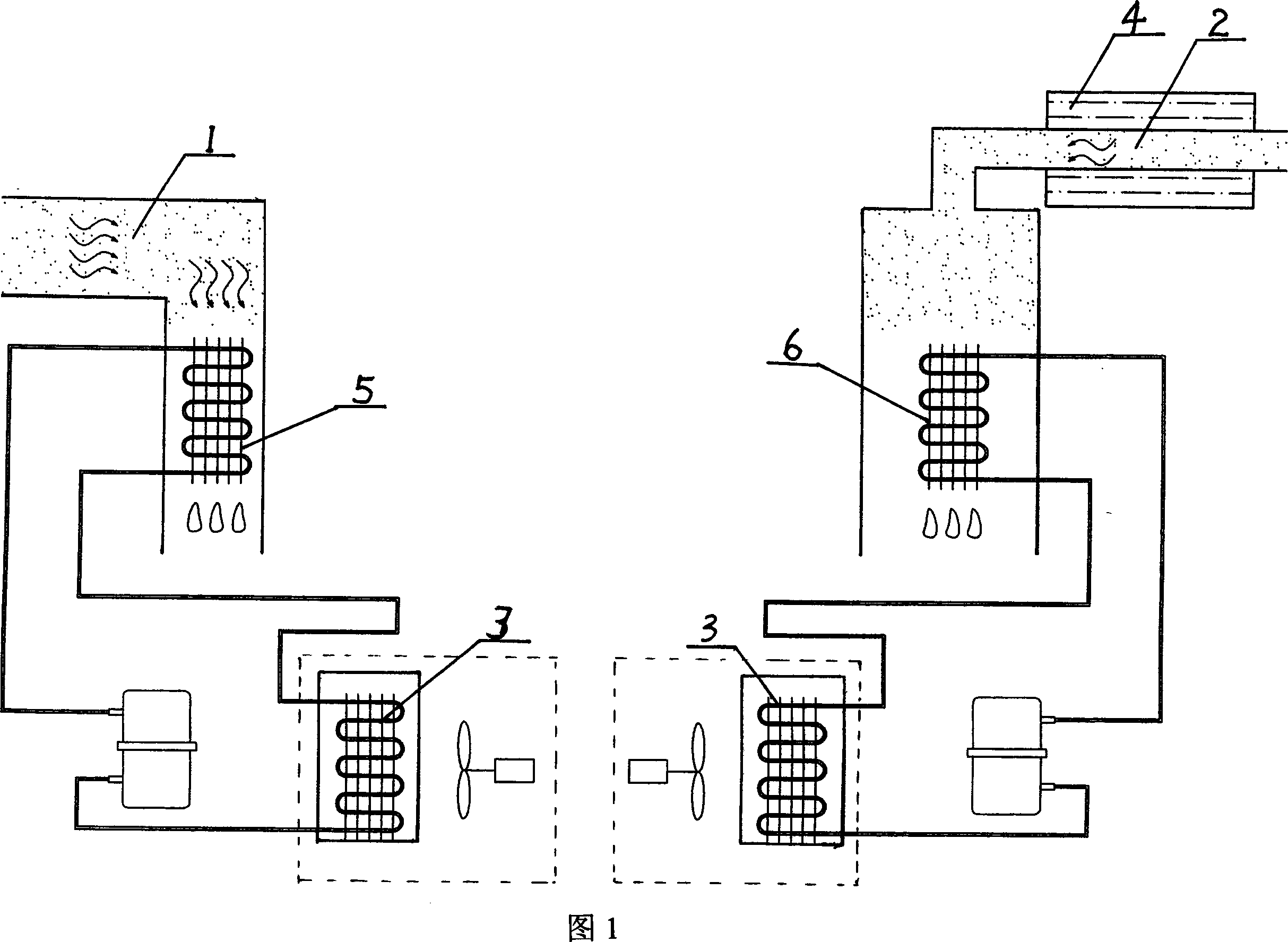
[0020] Embodiment 1, as shown in Figure 1, an air-cooled dry cleaning machine solvent recovery device, wherein the drying channel 1 and the distillation channel 2 are independent of each other, the two channels are respectively provided with a drying solvent cooling recovery device 5 and a distillation solvent Air-cooled heat exchangers 3 are respectively arranged in the circuits of the cooling recovery device 6 and the drying and distillation solvent cooling recovery devices 5 and 6 . When the device in this embodiment is used, since the distillation channel 2 is only communicated with the distillation cooling recovery device 6, the speed and efficiency of distillation cooling recovery solvent can be improved.
Embodiment 2
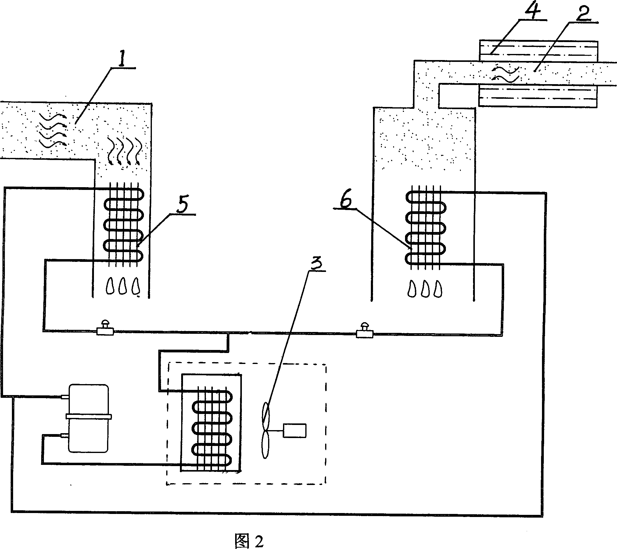
[0021] Embodiment 2, as shown in Figure 2, an air-cooled dry cleaning machine solvent recovery device, wherein the drying channel 1 and the distillation channel 2 are independent of each other, the two channels are respectively provided with a drying solvent cooling recovery device 5 and a distillation solvent An air-cooled heat exchanger 3 is provided after the cooling recovery device 6 and the circuits of the drying and solvent distillation cooling recovery devices 5 and 6 are connected. When the device in this embodiment is in use, because the distillation channel 2 is only communicated with the distillation solvent cooling recovery device 6, the speed and efficiency of the distillation cooling recovery solvent can be improved; The loops are connected to each other and share a set of air-cooled heat exchanger 3, therefore, its structure is more compact than that of Embodiment 1.
Embodiment 3
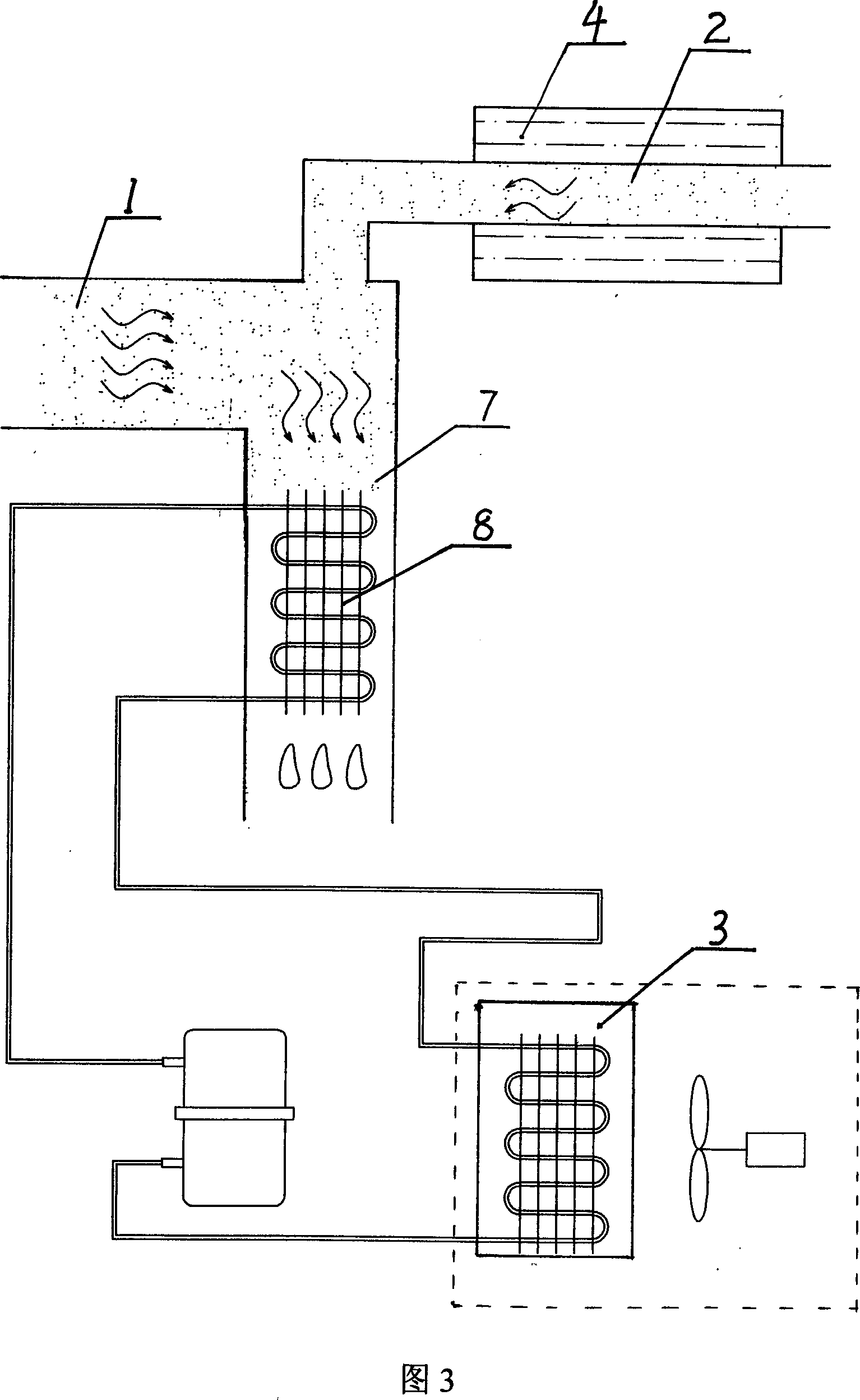
[0022] Embodiment 3, as shown in FIG. 3 , an air-cooled dry cleaning machine solvent recovery device, wherein the drying channel 1 and the distillation channel 2 are respectively connected with the cooling chamber 7, and a set of drying and distillation solvent is arranged in the cooling chamber 7. Cooling recovery device 8, air-cooled heat exchanger 3 is arranged in the circuit of drying distillation solvent cooling recovery device 8. In this embodiment, since the drying passage 1 and the distillation passage 2 communicate with the cooling chamber 7 and its drying and distillation solvent cooling recovery device 8, the structure is the most simple and practical, the solvent recovery efficiency is high, and the operation of the unit has been optimized.
[0023] As shown in Figure 4-6, that is, in Embodiments 4, 5, and 6, the heat exchangers described are all air-cooled heat exchangers 9, and the remaining structures correspond to the above-mentioned Embodiments 1, 2, and 3 resp...
PUM
 Abstract
Description
Claims
Application Information
 - R&D Engineer
- R&D Manager
- IP Professional
- Industry Leading Data Capabilities
- Powerful AI technology
- Patent DNA Extraction
Browse by: Latest US Patents, China's latest patents, Technical Efficacy Thesaurus, Application Domain, Technology Topic, Popular Technical Reports.
© 2024 PatSnap. All rights reserved.Legal|Privacy policy|Modern Slavery Act Transparency Statement|Sitemap|About US| Contact US: help@patsnap.com