Yarn feeder

A yarn feeder and sensor technology, used in textiles and papermaking, thin material handling, looms, etc., can solve problems such as hindering free entry, and achieve the effect of reducing design size, easy manufacturing, and improving work reliability

Inactive Publication Date: 2007-04-04
IRO AB
View PDF7 Cites 2 Cited by
  • Summary
  • Abstract
  • Description
  • Claims
  • Application Information

AI Technical Summary

Problems solved by technology

However, the concave design prevents free access from the sides, tends to collect lint between the lower surface and the associated storage area, and results in a relatively wide brake housing due to the V-shaped arrangement of the sensor components

Method used


Image

  • Yarn feeder
  • Yarn feeder
  • Yarn feeder

Examples


Embodiment Construction

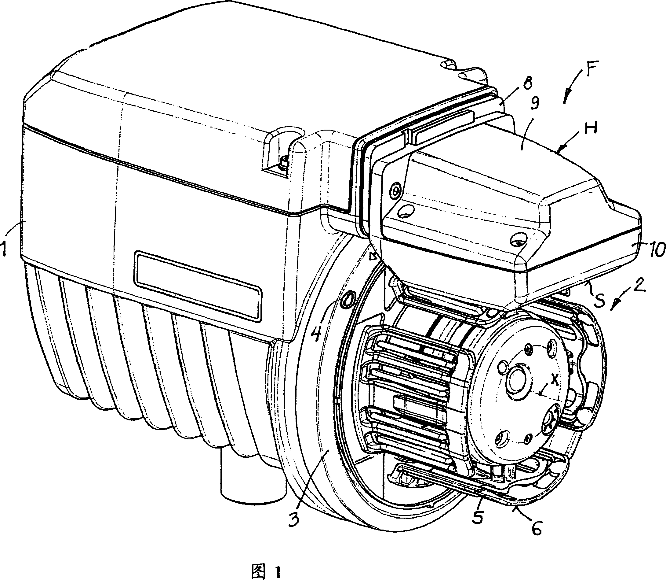
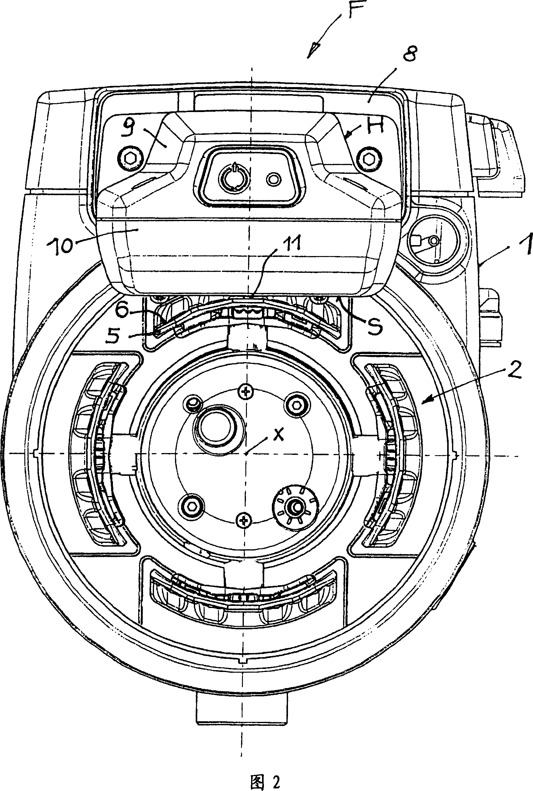
[0025] The yarn feeder F in Figs. 1 and 2, a so-called measuring conveyor, is used on a jet weaving machine (for example an air-jet loom) and comprises a housing 1 which is a section storage Body 2 provides fixed support. Between the housing 1 and the storage body 2 there is provided a rotatable winding element 3 (winding disc), and an output hole 4 from which the yarn, not shown, is drawn out and then wound on the adjacent storage body 2 or on the The separated yarns are wound on windings forming yarn packages on the storage body 2 . The storage body 2 is composed of segments 5 distributed along the circumference, each segment delimiting a concave storage area 6 . The segments 5 of the storage body are radially adjustable in order to vary the dynamic diameter of the storage body 2 .

[0026] The brake housing H is mounted to the front side of the housing 1 such that the brake housing H is associated with one segment 5 . For example the brake housing H is adjustable on the ...


PUM


Abstract

The lower surface (S) of a stopper housing (H) of a yam feeder (F) is continuously flat and essentially parallel to a tangent on the storage region (6) at the location of the stop element (11), and is, at least in a partial region, equipped with an abrasion resistant surface. The yarn feeder comprises a stationary storage body (2) provided at a casing (1), a storage surface on the storage body, the storage surface consisting of storage regions (6) arranged in circumferential direction around a storage body axis (X), a rotatable winding element (3, 4) between the casing (1) and the storage body (2), a stopper housing (H) supported by the casing (1), the stopper housing (H) having the lower surface (S) located adjacent to the storage surface with a yarn passing gap between the lower surface (S) and one storage region (6), a stopping device received in the stopper housing, a stop element (11) of the stopping device being movable through the lower surface (S) and the yarn passing gap towards the storage region, and at least one optoelectronic sensor assembly (20, 22, 24) received in the stopper housing, the sensor assembly including at least one transparent protector (17, 18) located in the lower surface (S) in the neighbourhood of the stop element (11).

Description

technical field [0001] The invention relates to a yarn feeder according to the preamble of claim 1 . Background technique [0002] In the prior art, this type of yarn feeder, that is, the measuring feeder of the so-called jet loom, the lower surface of the brake housing is a circular concave surface with a curvature similar to the storage surface, or it is made of a flat surface. The composition of the central region and the lateral regions inclined symmetrically with respect to the central region results in a generally concave design of the lower surface. In order to enable the positioning of the individual sensor assemblies as close as possible to the storage surface, a recessed surface shape is considered appropriate. However, the concave design prevents free access from the sides, tends to collect lint between the lower surface and the associated storage area, and results in a relatively wide brake housing due to the V-shaped arrangement of the sensor components. Cont...

Claims


Application Information

Patent Timeline
IPC IPC(8): D03D47/34B65H51/22D03D47/36
CPCD03D47/362B65H51/22D03D47/363D03D47/367
Inventor 杰拉尔多·索尔顿
Owner IRO AB
Why Eureka
Try Eureka