
Organic luminescent device and electrode base plate

An organic light-emitting device and electrode substrate technology, which can be applied to lighting devices, electroluminescent light sources, light sources, etc., can solve the problems of high cost, reduced pixel aperture ratio, difficulty, etc., and achieve the effect of increasing electrical conductivity and current carrying capacity

Inactive Publication Date: 2007-04-04
RITDISPLAY
View PDF0 Cites 5 Cited by
  • Summary
  • Abstract
  • Description
  • Claims
  • Application Information

AI Technical Summary

Problems solved by technology

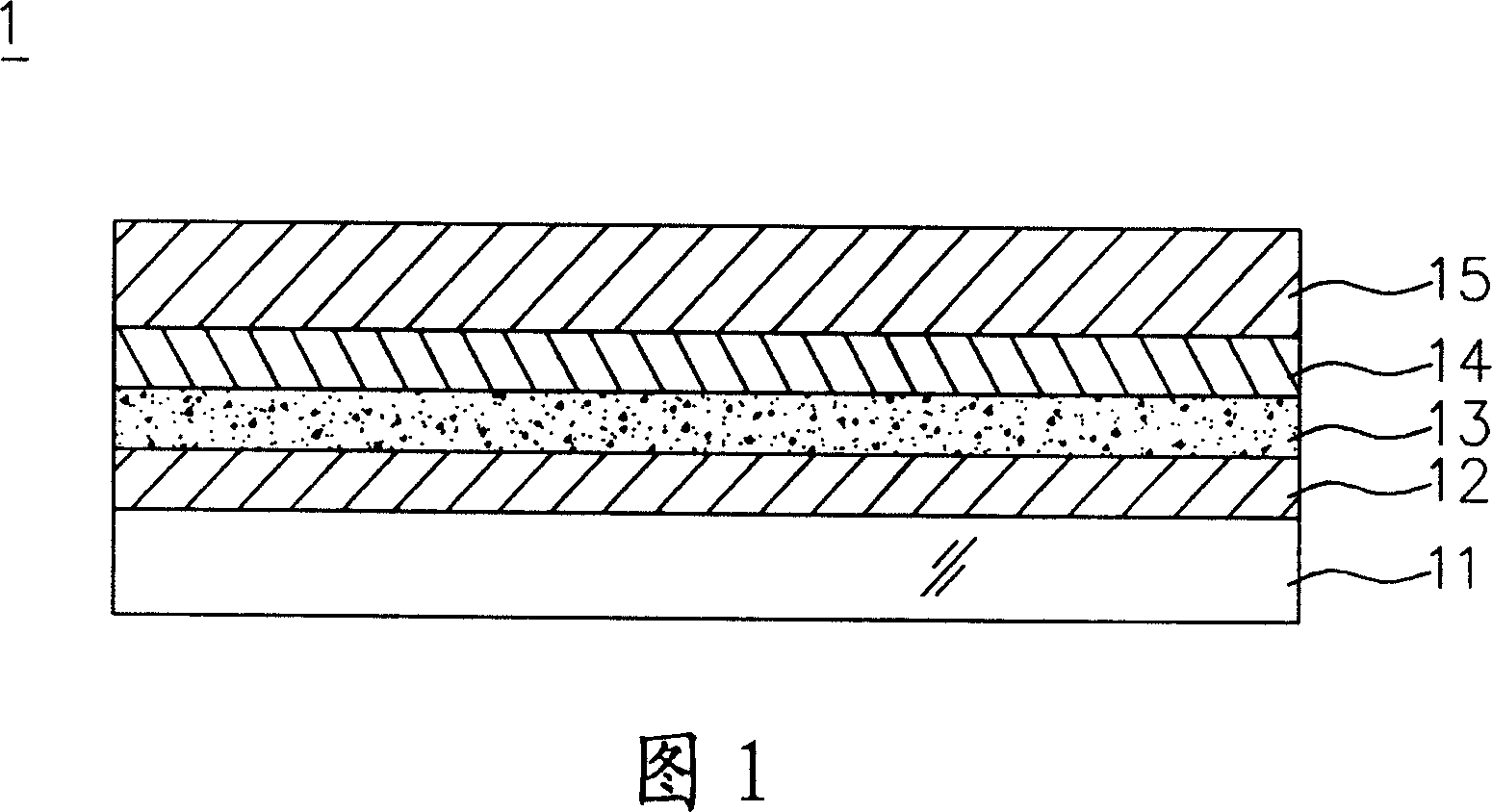
However, the current solution has the following two disadvantages: (1) since the organic light-emitting device 1 emits light from the top surface, the auxiliary electrode 15 disposed on the top surface will reduce the aperture ratio of the pixel; (2) since the auxiliary electrode 15 uses A mask (mask) is deposited on the second electrode 14. In order to manufacture a high-resolution organic light-emitting device 1, the size of the auxiliary electrode 15 must be relatively reduced. Dimensions are difficult and costly, and if the size of the auxiliary electrode 15 is too thin, the conductivity cannot be effectively increased

Method used


Image

  • Organic luminescent device and electrode base plate
  • Organic luminescent device and electrode base plate
  • Organic luminescent device and electrode base plate

Examples


no. 1 example

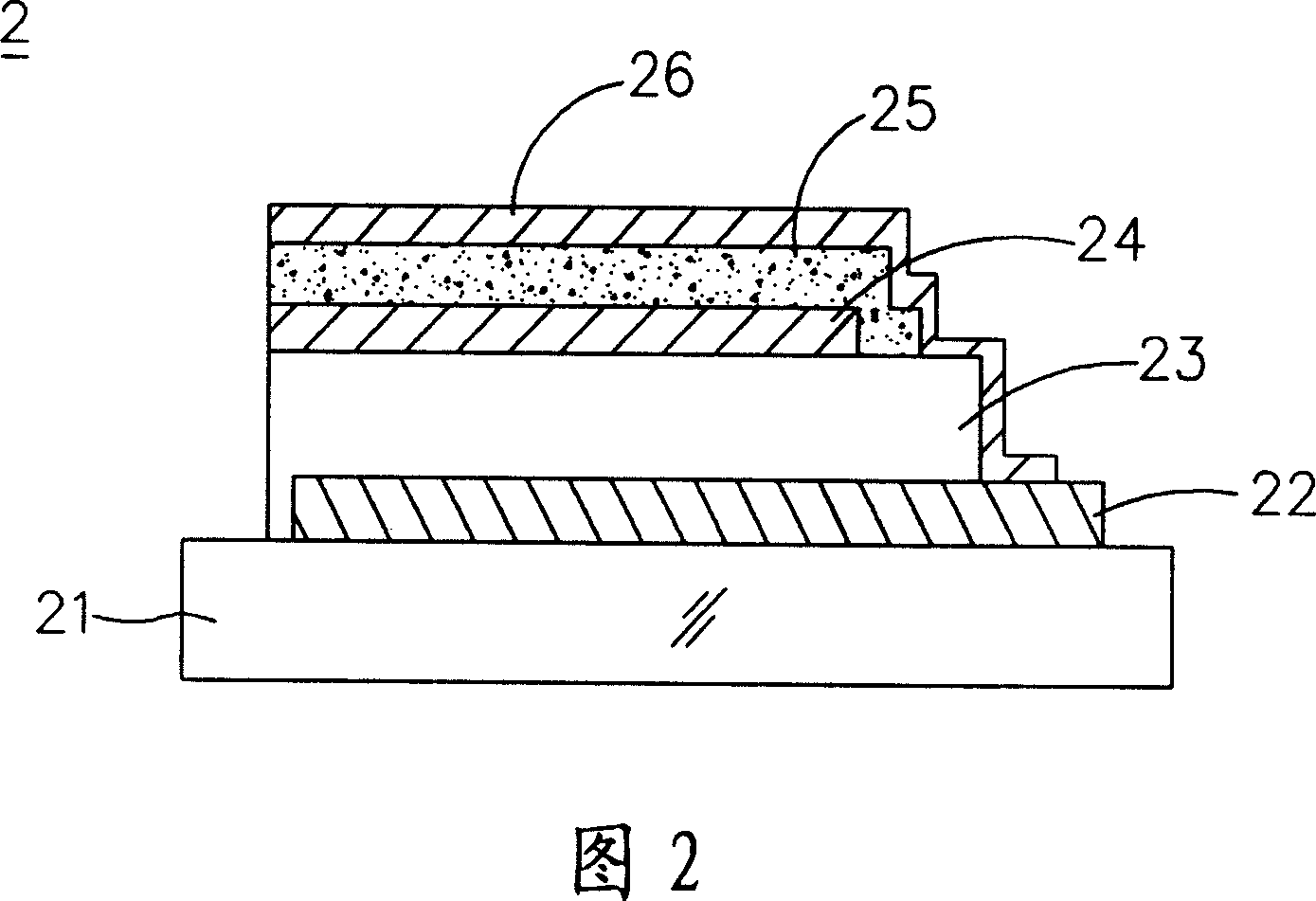
[0028] Please refer to FIG. 2, which is an organic light-emitting device 2 according to the first embodiment of the present invention, which sequentially includes a substrate 21, an auxiliary electrode 22, an insulating layer 23, a first electrode 24, an organic functional layer 25 and A second electrode 26 , wherein at least a part of the second electrode 26 is connected to the auxiliary electrode 22 .

[0029] In this embodiment, the substrate 21 may be a flexible substrate or a rigid substrate. Meanwhile, the substrate 21 can also be a plastic substrate or a glass substrate. Wherein, the flexible substrate and the plastic substrate can be polycarbonate (polyearbonate, PC) substrate, polyester (polyester, PET) substrate, cyclic olefin copolymer (cyclic olefin copolymer, COC) substrate or metal chromate substrate-cycloolefin Copolymer (metallocene-based cyclic olefincopolymer, mCOC) substrate. In addition, the substrate 21 may also be a silicon substrate.

[0030] In addit...

no. 2 example

[0038] In addition, as shown in FIG. 4 and FIG. 5 , an electrode substrate 3 according to the second embodiment of the present invention includes a substrate 31 , an auxiliary electrode 32 , an insulating layer 33 and an electrode 34 in sequence.

[0039] As shown in FIG. 5 , the electrode substrate 3 of this embodiment further includes a protection layer 35 disposed between the substrate 31 and the auxiliary electrode 32 .

[0040] The features and functions of the substrate 31 , the auxiliary electrode 32 , the insulating layer 33 , the electrode 34 and the protection layer 35 in this embodiment are the same as those in the first embodiment, and will not be repeated here.

[0041] As mentioned above, in the organic light-emitting device and the electrode substrate of the present invention, the auxiliary electrode is disposed under the organic functional layer. Compared with the conventional technology, since the auxiliary electrode of the present invention is arranged under th...


PUM


Abstract

The invention comprises a baseboard, an auxiliary electrode, an insulation layer, a first electrode, at least one organically-functionalized layer and a second electrode. The part of second electrode is connected to the auxiliary electrode.

Description

technical field [0001] The invention relates to a light-emitting device and an electrode substrate, in particular to an organic light-emitting device and an electrode substrate that emit light from a top surface. Background technique [0002] An organic light-emitting device (Organic Electroluminescent Device) is a device that utilizes the self-luminous properties of organic functional materials (organic functional materials) to achieve display effects. It can be divided into small molecule organic light-emitting devices ( Small molecule OLED (SM-OLED) and polymer light-emitting device (polymer light-emitting device, PLED) two categories. Due to the advantages of self-illumination, no viewing angle, power saving, easy manufacturing process, low cost, high response speed and full color, organic light-emitting devices have great application potential and are expected to become the next generation of flat-panel displays. [0003] Please refer to FIG. 1 , a conventional organic...

Claims


Application Information

Patent Timeline
Patent Type & Authority Applications(China)
IPC IPC(8): H05B33/12H05B33/14H05B33/26
Inventor 徐玉女杨富祥陈建兴
Owner RITDISPLAY
Learn More