Expansion dowel for fastening insulating panels

A thermal insulation material and expansion pin technology, applied in the direction of pins, screws, threaded fasteners, etc., can solve the problems of small balance value of expansion pins, thermal bridge formation, etc., and achieve an effect that is conducive to expansion

Inactive Publication Date: 2007-04-04
FISCHERWERKE ARTUR FISCHER GMBH & CO KG
View PDF0 Cites 5 Cited by
  • Summary
  • Abstract
  • Description
  • Claims
  • Application Information

AI Technical Summary

Problems solved by technology

[0003] The disadvantage of impact-driven expansion elements compared to screws is that the expansion pins partially achieve lower equilibrium values ​​(Haltewerte)
But these have the problem of forming thermal bridges

Method used


Image

  • Expansion dowel for fastening insulating panels

Examples


Embodiment Construction

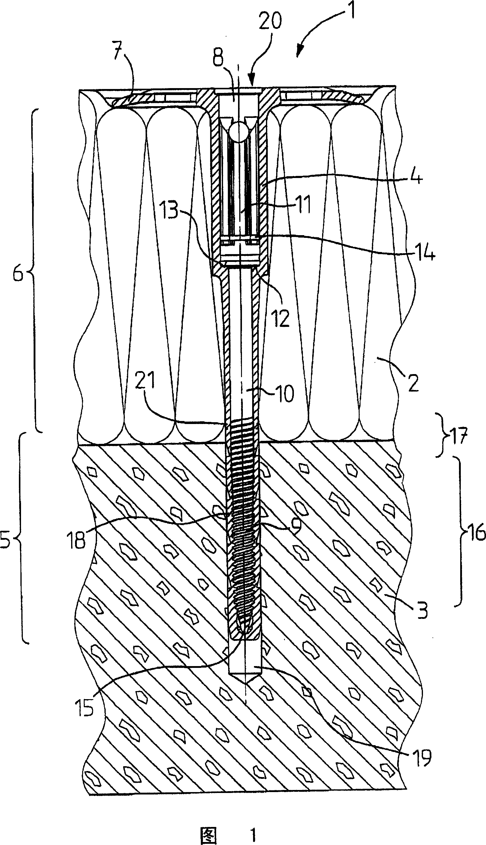
[0012] The only figure shows an expansion pin 1 according to the invention, which is used to fix a heat-insulating material plate 2 to a background 3. The expansion pin 1 has a pin sleeve 4, which has an expansion part 5, an extension section 6 and a stop disk 7 connected thereto. The expansion part may pass through a notch or expansion position arranged in the longitudinal direction, which is not shown. It is opened in the background 3 by the expansion screw 8, thus achieving the desired stopping effect. The expansion screw 8 is made of plastic and has a thread 9, a shank 10 connected thereto, and a head 11. The head 11 is supported on the pin shoulder 13 with a screw shoulder 12. The expansion screw 8 has a nominal breaking point 14 designed to surround the groove at its head. The outer diameter of the thread 9 of the expansion screw 8 protrudes from the outer diameter of the shank 10. It is slightly smaller than 1 / 3 of the pointing shank within 2 / 3 of the pointing screw tip 15....


PUM


Abstract

The anchor (1) has an expansion area (5), spreader unit (8), which is made up of plastics, and a retaining plate (7). The spreader unit is an expanding screw with a pull linkage at its header (11). The pull linkage is formed by a circulating groove in the header of the expanding screw. The expanding screw has a conical and cylindrical core section in an area of its screw thread.

Description

Technical field [0001] The invention relates to an expansion pin for fixing panels of insulating material having the features described in the preamble of claim 1. Background technique [0002] One such expansion pin is known from patent EP 1 457 688 A1. The known expansion pin has an expansion area followed by an extension with a stop disk. In order to fix the heat-insulating material board, first drill a hole through the heat-insulating material board to the background. Then, the expansion pin is inserted into the hole and anchored in the background by driving into the expansion member. The expansion member is a screw screw made of plastic, which can be hammered in with the aid of a drill bit used for drilling. Compared with the expansion member made of metal, the use of plastic has the following advantages: The expansion pin absolutely does not form a thermal bridge or the expansion pin itself has a thermal insulation effect like a heat-insulating material board. [0003] The ...

Claims


Application Information

Patent Timeline
IPC IPC(8): F16B13/04E04F13/08
CPCF16B13/124F16B33/006F16B31/021
Inventor J·伦茨
Owner FISCHERWERKE ARTUR FISCHER GMBH & CO KG
Why Eureka
Try Eureka