Eureka AIR delivers breakthrough ideas for toughest innovation challenges, trusted by R&D personnel around the world.

Desulfurizing absorbing separator

A separation device and separation tower technology, which is applied in separation methods, dispersed particle separation, chemical instruments and methods, etc., can solve the problems of large pressure loss, high operating cost, high moisture content, etc., and achieve stable matching dimensions, simplified The structure and the effect of easy replacement

Inactive Publication Date: 2007-04-04
陈鸣楼
View PDF0 Cites 0 Cited by
  • Summary
  • Abstract
  • Description
  • Claims
  • Application Information

AI Technical Summary

Problems solved by technology

Such as unstable treatment effect, large pressure loss, high moisture content, limited flue gas treatment capacity, large investment, high operating cost, etc.

Method used

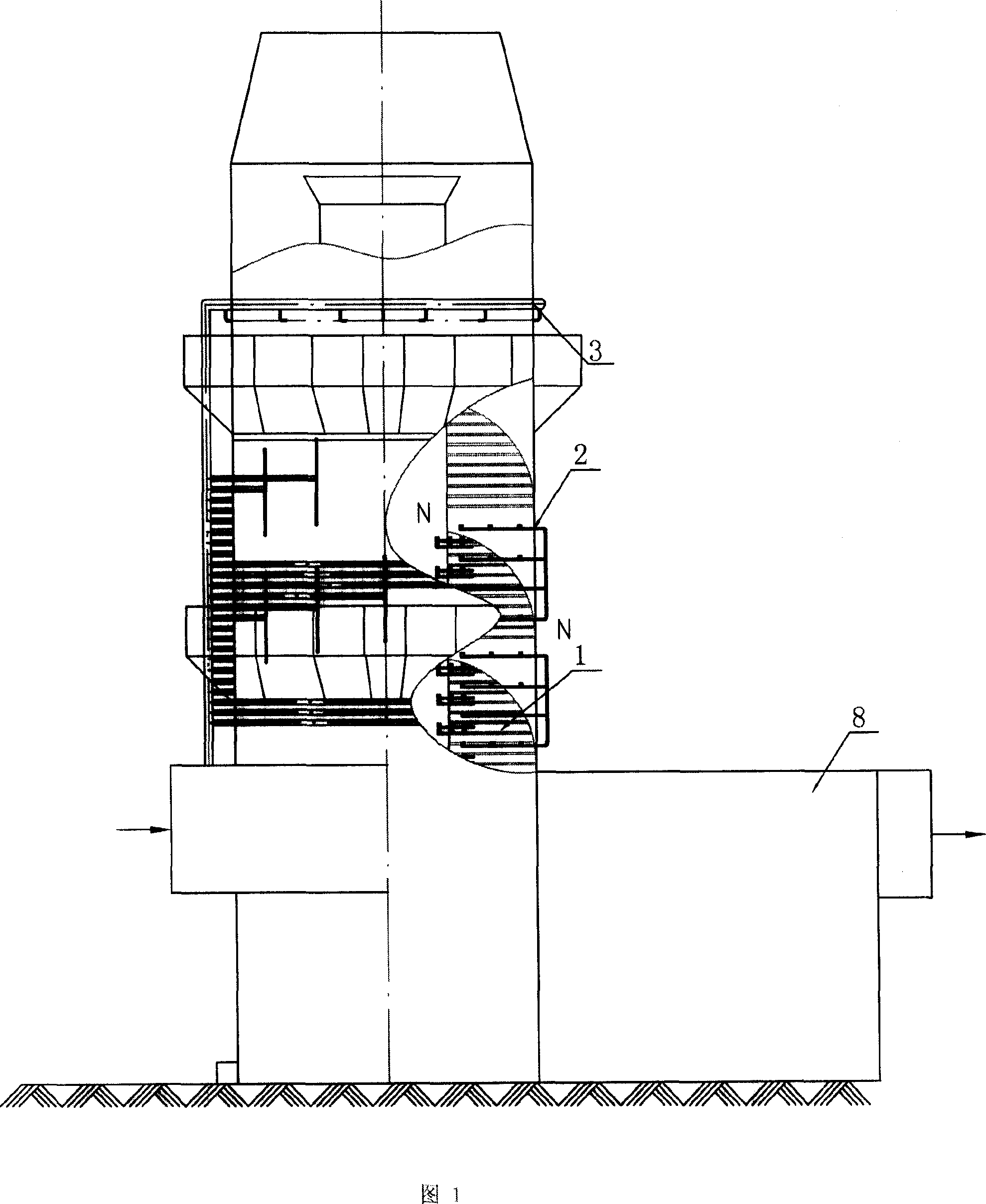
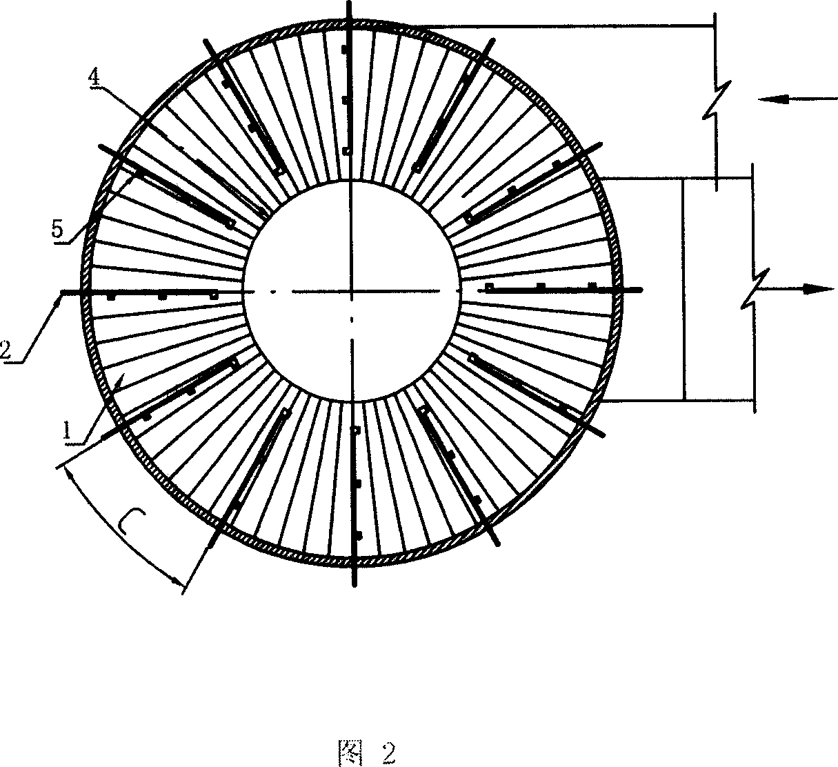
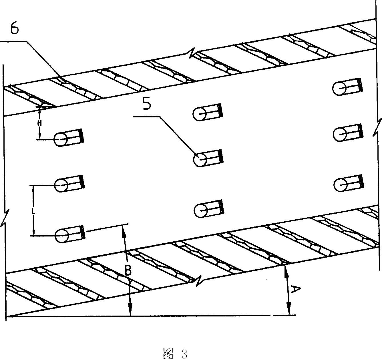

Image

  • Desulfurizing absorbing separator
  • Desulfurizing absorbing separator
  • Desulfurizing absorbing separator

Examples


Embodiment Construction

[0021] After the flue gas enters the desulfurization absorption and separation device, it contains SO 2 The flue gas enters the spiral passage formed by the swirl plate (6) between the outer cylinder and the centrifugal inner cylinder, and performs a spiral upward movement along the passage between the lower layer and the upper layer of the spiral swirl device (1). The spiral channel is divided into multiple sections, and a group of splash cone nozzles (5) are arranged on each section. Multiple sets of splash-cone nozzles form a spray system (2). The desulfurizer is sprayed out from the nozzle to form a liquid mist curtain. The splash cone nozzle (5) has a certain spray pressure, which can maximize the atomization of the sprayed absorption liquid, thereby reducing the droplet diameter, increasing the atomization coverage of this surface, increasing the mass transfer surface area, and prolonging the droplet diameter. Depending on the residence time of the flue gas in the towe...


PUM


Abstract

A sulfur removing and absorbing separator for treating fume is composed of a sulfur removing and absorbing separation tower for desulfurizing the fume, and a dreg removing case for further removing small particles and small liquid drops from fume. Said separation tower consists of external cylinder, internal centrifugal cylinder, and such units between said external and internal cylinders as spiral cyclone unit, sprinkling system and sputter plate type overflow unit.

Description

technical field [0001] The invention relates to flue gas SO in the environmental protection industry 2 Processing equipment, especially a desulfurization absorption separation device. Background technique [0002] The flue gas emitted by coal-fired boilers or other industrial kilns contains a large amount of SO 2 And dust, discharge after purification treatment, in order to avoid causing air pollution. At present, the most widely used flue gas treatment is wet desulfurization and dust removal equipment. Traditional equipment mainly includes spray towers, packed towers, jet bubble towers, liquid column towers, turbulent ball towers, Venturi tubes, porous towers, etc. Each of these devices has its own advantages and disadvantages. For example, the treatment effect is unstable, the pressure loss is large, the moisture content is high, the flue gas treatment capacity is limited, the investment is large, and the operating cost is high. Contents of the invention [0003] Th...

Claims


Application Information

Patent Timeline
Patent Type & Authority Applications(China)
IPC IPC(8): B01D53/18B01D53/50B01D53/78
Inventor 陈鸣楼
Owner 陈鸣楼
Why Eureka
Eureka Blog
Learn More