Lamp apparatus and lighting instrument
A lamp tube and lamp cap technology, applied in the field of lighting fixtures, can solve the problems of increasing the number of parts, increasing man-hours, etc., and achieve the effect of reducing manufacturing man-hours and reducing costs
- Summary
- Abstract
- Description
- Claims
- Application Information
AI Technical Summary
Problems solved by technology
Method used
Image
Examples
Embodiment 1
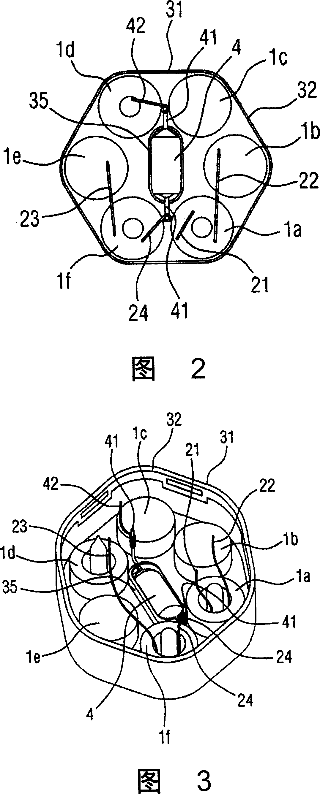
[0035] Next, embodiments of the lamp device of the present invention will be described with reference to the drawings. In each figure, the same reference numerals are attached to the same constituent elements, and overlapping descriptions are omitted. FIG. 1 is a front view showing an example of a lamp device of the present invention, and FIG. 2 is a plan view seen from the direction of arrow X in FIG. 1 . The lamp in the lamp device is composed of: using the connecting pipe 11, the glass lamp tubes 1a-1f formed by six straight tubes standing side by side and adjacent to each other here are combined, and the lamp tubes 1a-1f are formed by the connecting tube 11. To the lamp function with 1 discharge circuit. In this bulb, an inert gas such as argon (Ar) or krypton (Kr), or a gas containing mercury or the like is sealed.
[0036] A pair of electrodes 16 are encapsulated by tube sealing or compression sealing at respective one ends of the lamp tube 1a and the lamp tube 1f loca...
Embodiment 2
[0051] In the lamp device of the second embodiment, the electric wire 41 and the electric wire 24 ( 42 ) are reliably electrically connected by welding together with the lap connection.
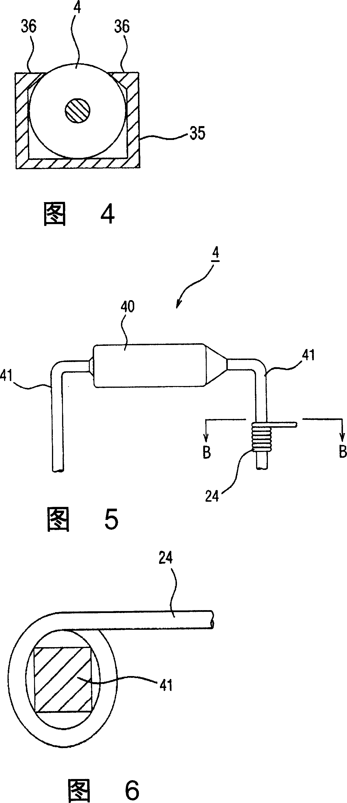
[0052] The outer electric wire of lamp device is that electric wire 24 (42) and the rod-shaped end wall in the temperature fuse 4 and is that the connection of electric wire 41 is to be connected by lap joint that electric wire 24 (42) is wound on electric wire 41, but in electric wire 24 ( 42) and 41, where the temperature of the connection part is 100°C or higher, when lap joints are used, the following provisions are made in accordance with the regulations of the Electrical Appliance and Material Safety Act.
[0053] Specifically, there is "For the connection of the part at... When the above is closely attached, when the corners of the terminal are in contact with more than 20 parts, and the entire wrapped wire is pulled toward the axial direction of the terminal with a force of 30N, the w...
Embodiment 3
[0059] In the first embodiment, the thermal fuse 4 is held by the claw piece 36 as shown in FIG. 4 , but it is common to use silicone resin or an adhesive material to fix the thermal fuse 4 in general lamps.
[0060] However, in the case of using a silicone resin or an adhesive material, since the thermal fuse 4 may be operated by heating and forced drying after coating the silicone resin or adhesive material, it cannot be used. Therefore, only a natural drying type can be used as a silicone resin or an adhesive material, but it takes a long time to dry, and it cannot be packed immediately after coating. If the lamp is moved in an incompletely dry state, the lamp may be dirty, and there is a worrying problem that the dry state has to be paid attention to. In addition, equipment and time for applying silicone resin or adhesive material are required, and the silicone resin or adhesive material required to fix the thermal fuse 4 is a problem that increases the lamp manufacturing ...
PUM
 Abstract
Description
Claims
Application Information
 - R&D Engineer
- R&D Manager
- IP Professional
- Industry Leading Data Capabilities
- Powerful AI technology
- Patent DNA Extraction
Browse by: Latest US Patents, China's latest patents, Technical Efficacy Thesaurus, Application Domain, Technology Topic, Popular Technical Reports.
© 2024 PatSnap. All rights reserved.Legal|Privacy policy|Modern Slavery Act Transparency Statement|Sitemap|About US| Contact US: help@patsnap.com


