Heat-conductive pipe and mfg. method

一种制造方法、热导管的技术,应用在半导体/固态器件制造、半导体器件、间接换热器等方向,能够解决热导管性能变异、不能工作介质充填量量化、未能提供真空度及注液量等问题,达到控制充填量的效果

Inactive Publication Date: 2007-03-28
FU ZHUN PRECISION IND SHENZHEN +1
View PDF0 Cites 15 Cited by
  • Summary
  • Abstract
  • Description
  • Claims
  • Application Information

AI Technical Summary

Problems solved by technology

Its ultimate goal is nothing more than to obtain a heat pipe with a high vacuum degree, but these methods cannot quantify the filling amount of the working medium.
In other words, the above-mentioned methods have not been able to provide a quantified vacuum degree and liquid injection volume so far, resulting in variations in the performance of the same batch of heat pipes

Method used


Image

  • Heat-conductive pipe and mfg. method
  • Heat-conductive pipe and mfg. method
  • Heat-conductive pipe and mfg. method

Examples


Embodiment Construction

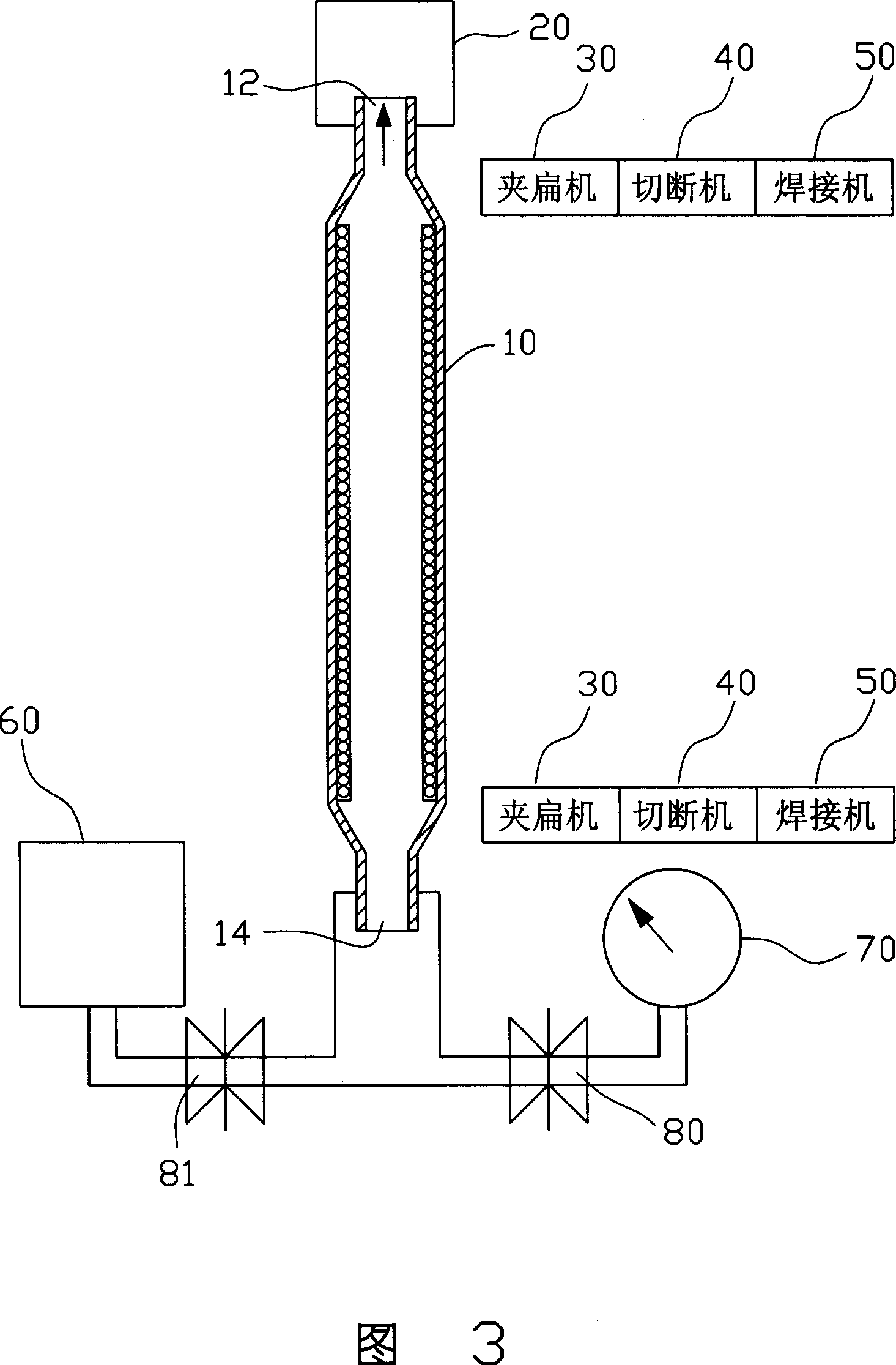
[0017] Please refer to FIG. 3 to FIG. 4 , which are schematic diagrams of the manufacturing device and sealing structure of the heat pipe of the present invention. The manufacturing device of the heat pipe includes a vacuum pump 20 , a clamping machine 30 , a cutting machine 40 , a welding machine 50 , a liquid injection tank 60 , a vacuum gauge 70 and a pair of valves 80 and 81 .

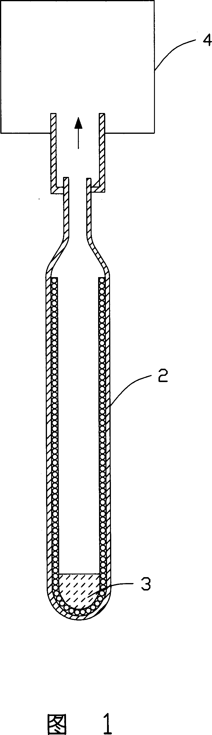
[0018] The operating principle of the manufacturing device of the heat pipe is as follows: firstly, the tube body 10 with the first opening 12 and the second opening 14 is placed in the vacuum suction tube and fixed with a base (not shown). The tube body 10 is provided with a capillary structure. Open the vacuum valve 80, close the liquid injection valve 81 and start the vacuum pump 20 to extract the gas in the tube body 10 from the first opening 12. The second opening 14 of the tube body 10 is equipped with a vacuum gauge 70, which shows the vacuum at the end of the tube body 10. Spend. When the...


PUM


Abstract

This invention relates to a heat conduction tube and its manufacturing method including the following steps: providing a tube with a first and a second open-end and fixing said tube, vacuuming said tube from the first open-end till the tube reaches to a pre-designed vacuum degree, sealing the first open-end to get a first sealed segment, injecting liquid from the second open-end and sealing it to get a second sealed segment. The heat conduction tube prepared by said method includes a sealed tube with a capillary structure and suitable working medium, in which, both ends of said tube are in staved sealed segments.

Description

【Technical field】 [0001] The invention relates to a heat pipe and a manufacturing method thereof. 【Background technique】 [0002] The vacuum degree of the heat pipe directly affects the response temperature of the latent heat of phase change, and the response temperature decreases with the increase of the vacuum degree; and the content of the working medium directly affects the maximum heat transfer (Qmax) and temperature difference (ΔT). [0003] As shown in Figures 1 and 2, the traditional heat pipe manufacturing method is to close one end of the heat pipe 2 and then place a certain amount of working medium 3 in the heat pipe 2, and use an external vacuum system 4 to remove the gas in the heat pipe 2. Pull it off, and finally use mechanical engagement, riveting, and welding to seal it. However, as the vacuum degree in the heat pipe 2 increases, the working medium 3 in it evaporates continuously, which makes it difficult to meet the high vacuum degree and further affects t...

Claims


Application Information

Patent Timeline
Patent Type & Authority Applications(China)
IPC IPC(8): F28D15/02F28D15/04
CPCH01L21/4882H01L23/427H01L2924/0002B23P15/26Y10T29/49353Y10T29/4935F28D15/0283Y10T29/53322Y10T29/53343Y10T29/53443B23P2700/09H01L2924/00
Inventor 侯春树童兆年刘泰健
Owner FU ZHUN PRECISION IND SHENZHEN
Why Eureka
Try Eureka