
Timer implementation method

An implementation method and timer technology, applied in the computer field, can solve the problems affecting the normal use of the timing function and the decrease of the timing accuracy of the timer, so as to prevent the timing accuracy from being too low, reduce the calling time, and ensure normal operation.

Active Publication Date: 2007-03-14
HUAWEI TECH CO LTD
View PDF0 Cites 10 Cited by
  • Summary
  • Abstract
  • Description
  • Claims
  • Application Information

AI Technical Summary

Problems solved by technology

However, if there are many tasks and the original timer of the system is used too frequently, the timing accuracy of the original timer will be greatly reduced, thus affecting the normal use of the timing function.

Method used


Image

  • Timer implementation method

Examples


Embodiment Construction

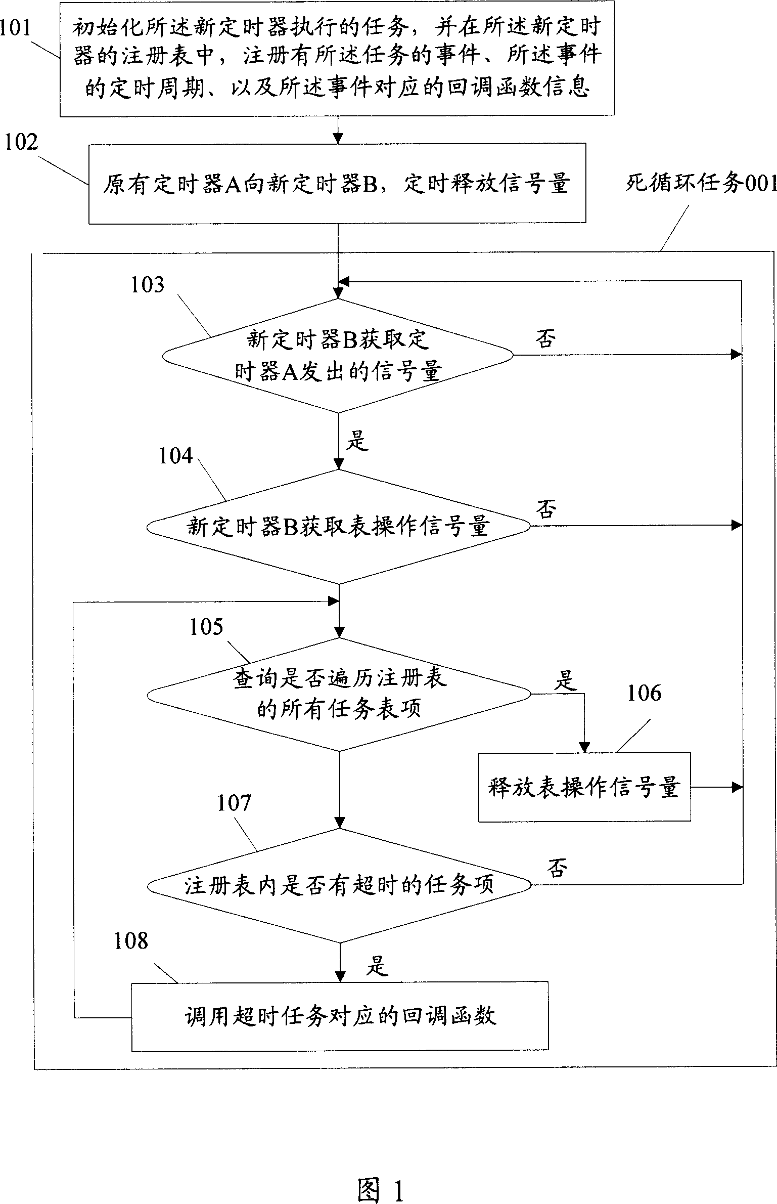
[0011] The purpose of the present invention is to solve the problem in the prior art that the original timer is called frequently, which causes the timing accuracy of the original timer to decrease. The core idea of ​​the present invention is to define a new timer in advance and initialize the new timer. The task executed by the timer, and the event of the task, the timing period of the event, and the callback function information corresponding to the event are registered in the registry of the new timer. The method includes: the new timer The timer acquires the semaphore regularly released by the original timer; the semaphore triggers the new timer, and the new timer inquires whether there is a timeout event in the registry preset in the timer , if there is, call the callback function corresponding to the event.

[0012] In order to enable those skilled in the art to better understand the content of the present invention, the content of the present invention will be further d...


PUM


Abstract

The related implementation method for a timer comprises: pre-defining new timer, initiating timer task, recording all events and timing cycle and recall function information in register; using the new-defined timer to obtain signal from original timer and trigger the new one; querying overt-time event from its register, yes to call the corresponding recall function. This invention reduces timer load and improves precision.

Description

technical field [0001] The invention relates to the field of computers, in particular to a method for realizing a timer. Background technique [0002] Timer is a common and necessary technology in software development. Timer is a collection of a series of functions. By using the methods provided by it, the software can complete the specified function within a fixed time. Its purpose is to make software automatically perform certain operations or tasks within a fixed period of time. Usually, high-precision timers are implemented by means of interrupts provided by hardware timers, which are also the most accurate benchmark timers in software systems. [0003] In general, in order to complete the function of "automatically performing certain operations within a fixed time" (for example: the function of sending and receiving data packets by the timer), the original timer of the software system is directly used. However, if there are many tasks and the original timer of the sys...

Claims


Application Information

Patent Timeline
IPC IPC(8): G06F9/44G06F9/46
Inventor 汤剑
Owner HUAWEI TECH CO LTD
Learn More