High-frequency high voice and strong sound wave blower

A technology of soot blower and strong sound wave, which is applied in the direction of sound-producing equipment, instruments, and treatment of combustion products, etc.

Active Publication Date: 2007-03-14
北京中电慧能国际电力科技有限公司
View PDF0 Cites 4 Cited by
  • Summary
  • Abstract
  • Description
  • Claims
  • Application Information

AI Technical Summary

Problems solved by technology

(4) The effective working temperature range is about 150-450°C, which is limited to use within the range of the rear flue of the economizer of the boiler

Method used


Image

  • High-frequency high voice and strong sound wave blower

Examples


Embodiment Construction

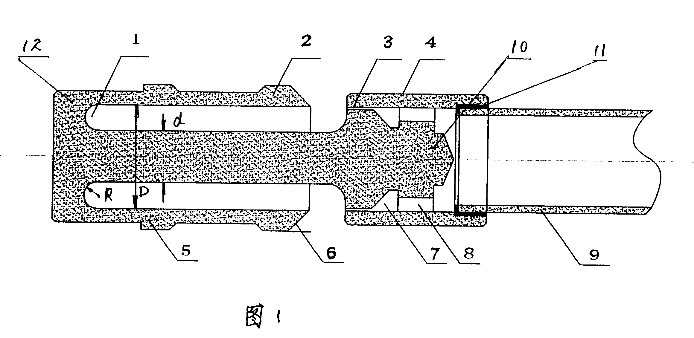
[0009] The structure schematic diagram of the high-frequency high-sound intensity sootblower proposed by the present invention is shown in FIG. The resonant cavity cap 12, the airflow ring cover 4 and the air guide tube 9 are installed coaxially in sequence. The outer wall of the resonant cavity cap 12 is provided with a resonant cavity rectifying ring 5, the end of the resonant cavity cap is a turbulent flow ring 2, and the included angle α between the resonant wedge 6 at the end of the turbulent flow ring 2 and the extension line of the outer wall of the turbulent flow ring is 25°~ 70°. The center of the resonant cavity cap 12 is a support concentric rod 10, and an annular resonant cavity 1 is formed between the root of the support concentric rod 10 and the inner wall of the resonant cavity cap. One end of the airflow ring cover 4 and the inner wall of the airflow ring cover 4 form an annular gap 3 , an air chamber 7 and a guide hole 8 in sequence. The end of the guide tub...


PUM


Abstract

The invention relates to an acoustic soot blower with high frequency and sound intensity, belonging to boiler equipment technological area. The blower comprises resonance cavity cap, gas-ring cover and air duct. They are concentrically installed in turn. On the outside of resonance cavity cap integral ring for resonance cavity is set and the end of resonance cavity cap is turbulent flow ring. One supporting concentric bar is set on the center of resonance cavity cap and circular resonance cavity, whose bottom is arc-shaped, is formed by the roof of the bar and the inner of resonance cavity cap. The frontal end of the supporting concentric bar extends into the end of gas-ring cover and circular gap, air room and diversion hole are formed by the supporting concentric bar and the inside of gas-ring cover. The end of air duct extends into the other end of gas-ring cover. In the invention, there are no any rotary parts and no need to e maintained in industrial scene. Dried saturated steam or compressed air is used as the driving source for acoustic soot blower. The soot blower is set on the furnace wall of boiler or in the boiler so as to reach optimal soot-blowing performance.

Description

technical field [0001] The invention relates to a high-frequency, high-sound-intensity sonic soot blower, which belongs to the technical field of boiler equipment. Background technique [0002] In various boiler equipment (including power plant boilers and industrial boilers, coal-fired boilers and oil-fired boilers), on the surfaces of the heat exchangers in the furnace and flue, almost without exception, ash deposits and slagging phenomena occur. Ash, slag The accumulation of accumulated coal reduces the thermal efficiency of the boiler, and in severe cases, it will also affect the safe operation of boilers and other equipment, forcing the boiler to be shut down for manual coke and slag removal, thereby reducing the utilization rate and service life of the boiler and increasing the labor intensity of workers Even casualties occurred. Faced with this long-standing and difficult problem that has existed in various boilers for a long time, various boiler soot blowers have be...

Claims


Application Information

Patent Timeline
IPC IPC(8): F23J3/00G10K11/00
Inventor 张晨韩淑华张举
Owner 北京中电慧能国际电力科技有限公司
Why Eureka
Try Eureka