Scrap-cutting conveyor with cooling liquid filtering apparatus

A filtering device and cooling liquid technology, applied in the direction of conveyor objects, filtration separation, fixed filter element filter, etc., can solve the problems such as difficult to clean chips

Inactive Publication Date: 2010-05-05
DOOSAN MACHINE TOOLS CO LTD
View PDF7 Cites 1 Cited by
  • Summary
  • Abstract
  • Description
  • Claims
  • Application Information

AI Technical Summary

Problems solved by technology

However, the problem with the filter system of this chip conveyor is that it is not easy to clean the chips

Method used


Image

  • Scrap-cutting conveyor with cooling liquid filtering apparatus
  • Scrap-cutting conveyor with cooling liquid filtering apparatus
  • Scrap-cutting conveyor with cooling liquid filtering apparatus

Examples


Embodiment Construction

[0026] Preferred embodiments of the present invention will be described in detail below with reference to the accompanying drawings.

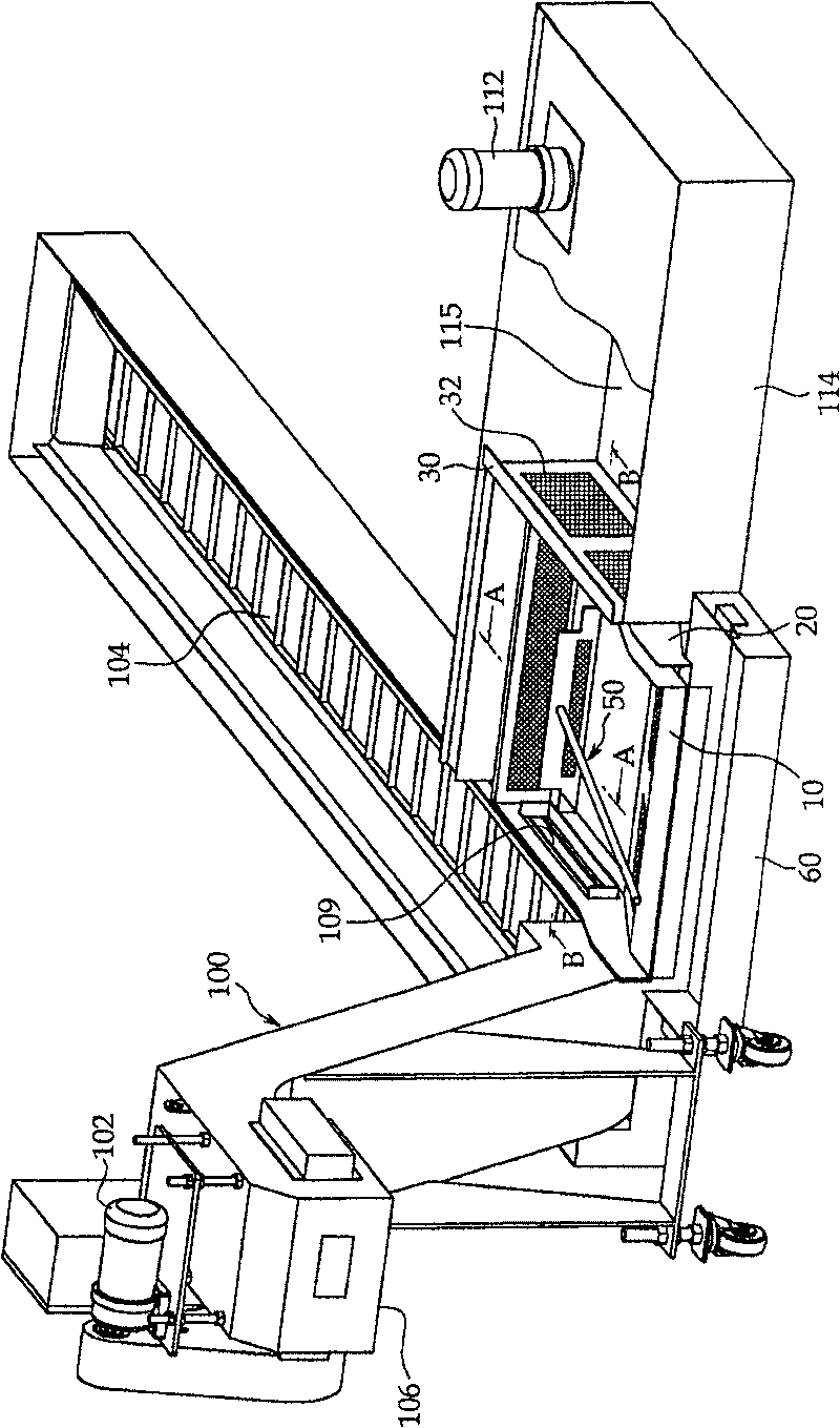
[0027] applied to the present invention figure 1 The chip conveyor 100 is a recirculation device that separates the coolant discharged from the processing machine (not shown) together with the chips into the chips and the coolant, discharges the chips to the outside of the processing machine, and sends the coolant to the following The coolant tank 114.

[0028] The chip conveyor 100 includes a chip belt 104 for delivering coolant to a chip outlet 106, and an opening 109 formed on one side of the chip belt 104 for discharging the coolant containing some chips, the coolant together with the chips Discharged from the processing machine together.

[0029] The chips and coolant flowing from the chip belt 104 to the sidewall are discharged through the opening 109, and the chips and coolant discharged through the opening 109 flow into the chip coll...


PUM


Abstract

The present application discloses a scrap-cutting conveyor, the conveyor separates cooling liquid that discharged from processing machine with scrap into scrap and cooling liquid, discharges the scrapto the outside of the processing machine, and uses the cooling liquid circularly. The scrap-cutting conveyor comprises: conveyor, which includes a conveyer belt for conveying the cooling liquid to the output port of the scrap, and hatch for discharging the cooling liquid that contains scrap; scrap collecting device for receiving the cooling liquid discharged from said hatch, the scrap collectingdevice has a scrap filter for collecting the scrap in the cooling liquid and discharging the cooling liquid to the cooling liquid box; and cooling liquid box for receiving said conveyor and scrap collecting device from bottom to top, the cooling liquid box includes pump inhalation chamber that separates with said scrap collecting device.

Description

technical field [0001] The present invention relates to a chip conveyor with a coolant filter for discharging chips produced by a processing machine, in particular to such a chip conveyor with a coolant filter in which by using a detachable multi-layer filter removes fines easily and cleans the filter easily. Background technique [0002] Coolant and swarf are generated when a machine tool or processing machine cuts a workpiece. The coolant goes through a recovery cycle, where the coolant is sucked into the coolant pump for recirculation, and the chips are collected on one side by the chip discharge unit. [0003] Typically, chip conveyors adapted to discharge long chips include a filter device mounted integrally with the coolant tank with the filter. [0004] Figure 8 and Figure 9 The structure of a conventional chip conveyor is shown in . exist Figure 8 A chip conveyor 100 , shown in perspective view of , receives chips and expels them to a chip outlet 106 using a c...

Claims


Application Information

Patent Timeline
Patent Type & Authority Patents(China)
IPC IPC(8): B23Q11/00
CPCY02P70/10B01D21/0012B01D29/01B23Q11/0053B23Q11/0067B23Q11/1069B65G47/34
Inventor 辛泳东金光振
Owner DOOSAN MACHINE TOOLS CO LTD
Why Eureka
Try Eureka