
Filter device

A filter device and filter technology, applied in the direction of filtration separation, membrane filter, cartridge filter, etc., can solve expensive problems

Inactive Publication Date: 2007-02-28
IBS菲尔特兰塑料金属产品有限责任公司
View PDF1 Cites 17 Cited by
  • Summary
  • Abstract
  • Description
  • Claims
  • Application Information

AI Technical Summary

Problems solved by technology

However, this combination of two filters is more expensive

Method used


Image

  • Filter device
  • Filter device
  • Filter device

Examples


Embodiment Construction

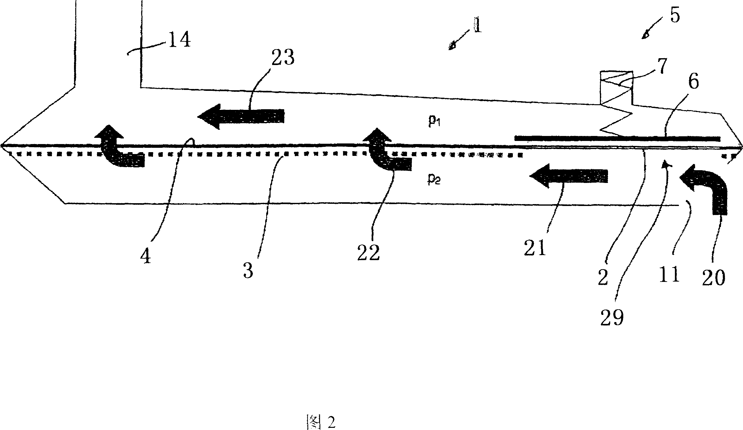
[0030] FIG. 1 shows a cross-sectional view of a first embodiment of a filter device 1 designed as an oil filter with a filter housing 10 and an inlet 11 and an outlet 14 for the fluid flowing through the filter device 1 . In the filter device 1 , a filter medium with a bypass 29 is provided between the inlet 11 and the outlet 14 . The filter medium has a first filter medium 4 in the form of the finest filter. A second filter medium 2 is arranged on the bypass 29, which medium is designed in the form of a coarse filter. A third filter medium 3 in the form of a fine filter can optionally be provided as a prefilter in the flow direction before the first filter medium.

[0031] For regulating the volume flow via the bypass 29, there is a control device 5 with the plate 6 as the shutter body and the spring 7 as the regulating device. Said spring 7 is connected to the plate 6 so that the plate 6 is pressed in the direction towards the coarsely filtered second filter medium 2 and a...


PUM


Abstract

The present invention relates to a filter device for filtering a fluid, in particular an oil filter. It has at least one filtering medium and a bypass for the filtering medium. Furthermore, an actuator is provided, which influences the flow of the fluid through the bypass as a function of a predetermined parameter of the fluid. The actuator is preferably controlled as a function of the viscosity of the fluid, a differential pressure of the fluid at the filtering medium, and / or the temperature of the fluid.

Description

technical field [0001] The invention relates to a filter device for filtering fluids, such as an oil filter, having at least one filter medium and a bypass for the filter medium. Background technique [0002] US4402827 discloses the construction of a vacuum oil filter with a finely filtered filter medium and a bypass for use in an automatic transmission and on which a coarse filter medium is also provided. At low temperatures, if the fluid viscosity is high, it can flow through the coarse filter media with little pressure drop. At high temperatures, if the fluid is less viscous, it can flow through fine filter media for higher filtration efficiency. [0003] In this configuration, however, there is always a side stream flowing through the coarse filter medium, even at high temperatures, so that only a small fluid purification effect can be obtained for this part. However, due to the increasing demands placed on automatic transmissions or internal combustion engines in term...

Claims


Application Information

Patent Timeline
IPC IPC(8): B01D35/147F16H57/04
CPCB01D35/0273F16H57/0402B01D2201/188B01D35/147B01D39/00B01D27/00
Inventor 马库斯·贝尔米夏埃多·雅各布米夏埃多·德德林沃尔夫冈·施陶斯贝格
Owner IBS菲尔特兰塑料金属产品有限责任公司
Learn More