
Light installation of microwave sulfur lamp

A lighting device and microwave technology, which is applied in the field of electric light sources, can solve the problems of inability to concentrate microwave energy, unfavorable energy absorption, and large system volume, and achieve the effects of compact structure, improved utilization rate, and reduced device volume

Inactive Publication Date: 2007-02-21
LG ELECTRONICS (TIANJIN) APPLIANCES CO LTD
View PDF0 Cites 7 Cited by
  • Summary
  • Abstract
  • Description
  • Claims
  • Application Information

AI Technical Summary

Problems solved by technology

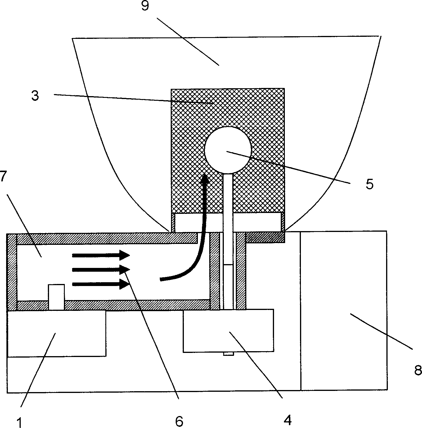
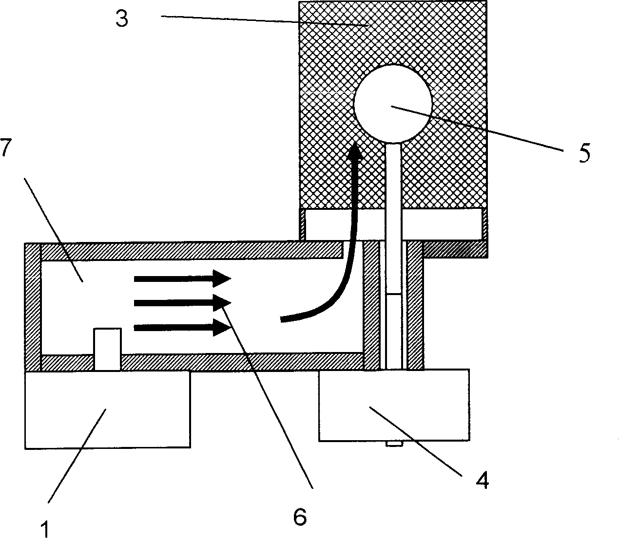
The disadvantages of the above-mentioned existing microwave sulfur lamp lighting device are: the position of the coupling hole deviates from the center of the bottom surface of the resonant cavity, and the microwave energy entering the resonant cavity cannot be concentrated on the point light source at the center, which is not conducive to energy absorption, and the system volume is relatively large. Inconvenience to use

Method used


Image

  • Light installation of microwave sulfur lamp
  • Light installation of microwave sulfur lamp
  • Light installation of microwave sulfur lamp

Examples


Embodiment Construction

[0018] Below in conjunction with accompanying drawing and specific embodiment the present invention is described in further detail:

[0019] image 3 It is a structural schematic diagram of the microwave sulfur lamp lighting device of the present invention; Figure 4 It is a schematic cross-sectional view of a microwave sulfur lamp lighting device of the present invention; Figure 5 It is a structural schematic diagram of the hard coaxial in the present invention.

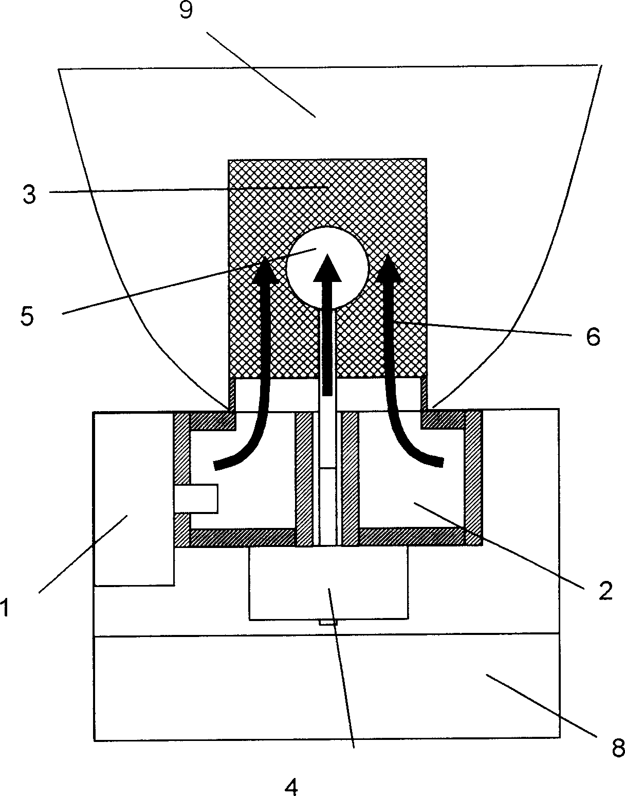
[0020] Such as image 3 , Figure 4 and Figure 5 As shown, the lighting device of the microwave sulfur lamp includes: a magnetron 1 arranged inside the casing to generate microwave energy under the action of electricity; a resonant cavity 3 capable of resonating microwave energy; The quartz bulb 5 excited by microwave energy to emit light, and the bulb motor 4 that drives the quartz bulb 5 to rotate; also includes the hard coaxial 2 that microwave 6 can be evenly introduced into the resonant cavity 3 from the...


PUM


Abstract

The illuminating apparatus of microwave sulfur lamp includes following parts: being setup inside chassis, magnetron of generating microwave energy under action of electric power; resonant cavity of making resonance of microwave energy; being setup inside the resonant cavity, quartz bulb glows caused by excitation from microwave energy; electrical motor of driving quartz bulb to be rotated; rigid coaxial set to let microwave enter to resonant cavity evenly from central position of underside of the resonant cavity. Rigid coaxial set is adopted to transfer microwave. Thus, microwave energy is converged to spot light source at central portion so as to reduce difficulty to excite plasma. The invention increases coupling capability between microwave energy and light source. Advantages are: raised use ratio of energy, compact structure so as to be in favor of miniaturization of product.

Description

technical field [0001] The invention relates to an electric light source; in particular, it relates to a lighting device for a microwave sulfur lamp. Background technique [0002] The lighting device of the current microwave sulfur lamp has a structure such as figure 1 and figure 2 As shown, it includes a magnetron 1, a rectangular waveguide cavity 7, a resonant cavity 3, a quartz bulb 5 and a bulb motor 4; when the power supply 8 is turned on, the magnetron 1 generates microwaves 6 under DC high voltage drive, and the microwaves pass through the rectangular waveguide cavity 7 The coupling hole is introduced into the resonant cavity 3, and the microwave is coupled with the sulfur plasma contained in the quartz bulb 5 in the resonant cavity to excite sulfur molecules to radiate, stimulate the quartz bulb 5 to emit light, and reflect the light by the reflector 9; in order to make The plasma works uniformly and stably, and the quartz bulb is driven by a motor to rotate at hi...

Claims


Application Information

Patent Timeline
IPC IPC(8): H01J65/00
Inventor 李元鹤宋奇伦
Owner LG ELECTRONICS (TIANJIN) APPLIANCES CO LTD
Learn More