Ash removal equipment for flapping exhaust heat boiler

A technology of dust removal device and waste heat boiler, which is applied in the fields of removal of solid residue, lighting and heating equipment, and treatment of combustion products. The operation of the equipment is stable and reliable, the dust cleaning ability is good, and the use is reliable and safe.

Active Publication Date: 2007-02-21
HANGZHOU BOILER GRP CO LTD +1
View PDF0 Cites 10 Cited by
  • Summary
  • Abstract
  • Description
  • Claims
  • Application Information

AI Technical Summary

Problems solved by technology

At present, this type of boiler has the following three cleaning methods: one is sonic cleaning, that is, sound waves of a certain frequency are emitted to the heating surface space at regular intervals, and the flue gas flow is strongly disturbed to achieve the effect of cleaning the heating surface. However, this method of removing dust deposits cannot be continuously cleaned, and the effect of cleaning dust on different parts of the heating surface is very different, and there are many blind spots, and due to the large negative pressure of the boiler, a large amount of cold air will be brought in when emitting sound waves. Seriously affects the thermal efficiency of the boiler; in addition, the applied stress values ​​of different parts of the heating surface due to the sound wave vibration are very different, so that the anti-fatigue life is different; the second is the blasting cleaning method, its principle is similar to the sound cleaning Using a certain amount of explosive shock waves instead of sound waves, it also has the same disadvantages as the above-mentioned cleaning method, and the blasting force is difficult to control, and the local heating surface is easily damaged; the third is the mechanical vibration cleaning method, and its working principle is: The rapping hammer periodically hits the rapping rod that is in close contact with the heating surface to make the tube group on the heating surface vibrate as a whole, and the vibration mechanical wave is transmitted to each geometric point along the axial direction of the tube on the heating surface, so as to achieve the purpose of dust removal , which has the advantage that the generation and transmission of mechanical waves are evenly distributed in time and space, and has an extremely good cleaning effect; but the mechanical vibration cleaning mechanism is still immature, and there are many problems as follows: , easy to damage the heating surface; easy to cause jamming due to thermal expansion; there are problems with flexible sealing and durability; there are problems such as vibration anti-loosening and vibration wear, and it is urgent to improve in many aspects

Method used


Image

  • Ash removal equipment for flapping exhaust heat boiler
  • Ash removal equipment for flapping exhaust heat boiler
  • Ash removal equipment for flapping exhaust heat boiler

Examples


Embodiment Construction

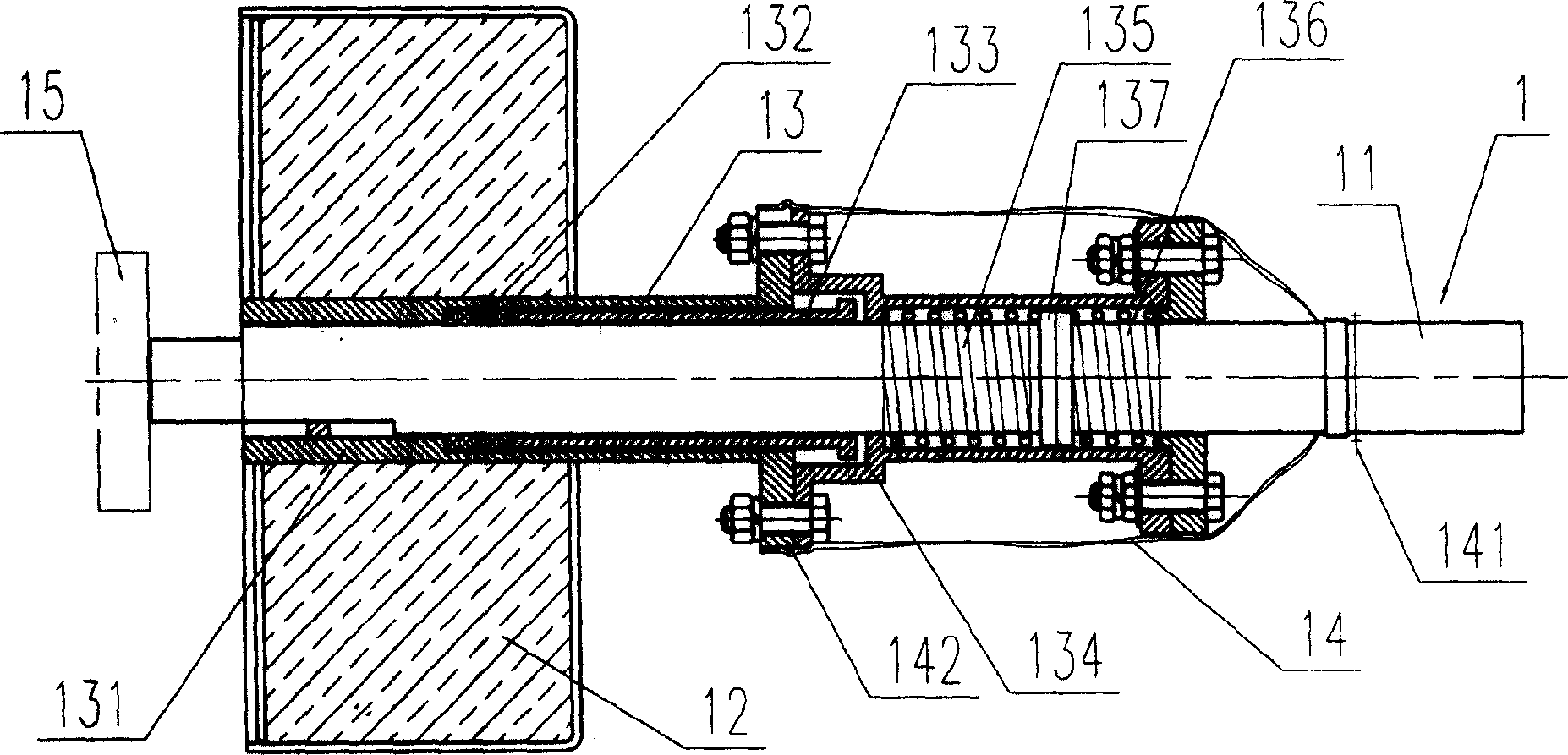
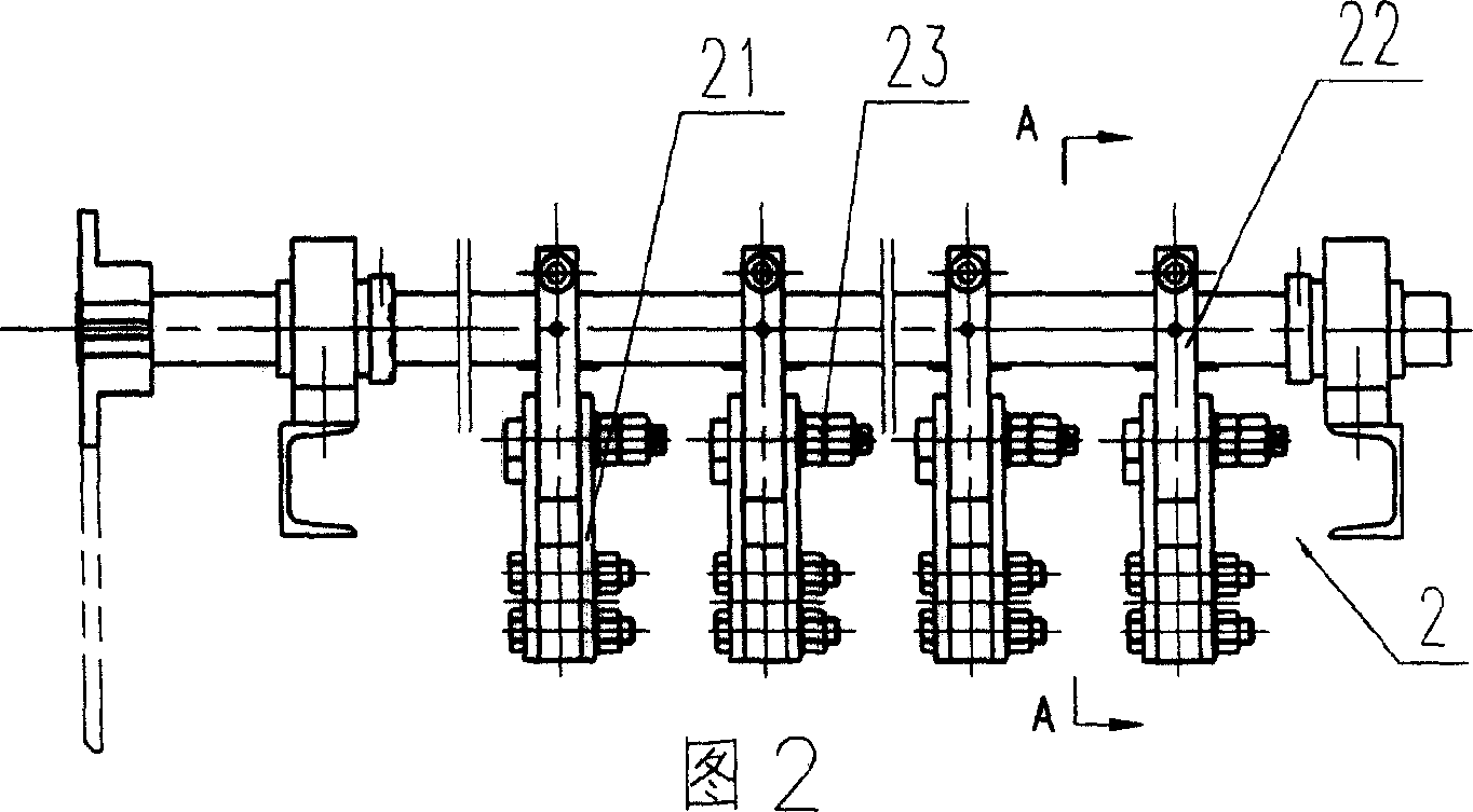
[0015] The present invention will be described in detail below in conjunction with the accompanying drawings: the present invention mainly consists of a rapping rod mechanism 1, a rapping hammer mechanism 2 and a motor transmission mechanism. figure 1 As shown, the rapping rod mechanism 1 includes a rapping rod 11 with one end in contact with the rapping surface. The rapping rod 11 passes through the wall of the heat preservation box 12 and is provided with a sealing device 13 . The sealing device 13 includes a guide sleeve 131 fixed on the wall of the insulation box 12, the rapping rod 11 passes through the guide sleeve 131, and an oil-soaked asbestos disc is arranged between the guide sleeve 131 and the rapping rod 11 Root 132.

[0016] The outside between the guide sleeve 131 and the rapping rod 11 is also sleeved with a pressure sleeve 133, and the outside of the pressure sleeve 133 is provided with a left and right two sleeves placed on the rapping rod 11 by the spring sl...


PUM


Abstract

A rapping device for removing off ash of residual heat boiler consists of rapping rod mechanism including rapping rod contacting with rapped surface by one end of rapping rod, sealing unit set on rapping rod at position before said rod is passed through insulation box wall and spring set on rapping rod; rapping hammer mechanism including vibration-loose proof unit set on said hammer, pin shaft for connecting said hammer with link bar and nut for fixing them; and motor driving mechanism.

Description

technical field [0001] The invention relates to a mechanical rapping device for removing dust accumulation on the heating surface of a boiler by continuous rapping, especially the mechanical rapping device for the heating surface of a cement kiln waste heat boiler, so as to ensure the heat transfer efficiency of the heating surface. Background technique [0002] Waste heat boilers, especially cement kiln waste heat boilers, have a very high dust content in the flue gas, and the flue gas temperature is below 400°C. How to effectively and continuously remove the dust on the heating surface is the key to the stable operation of this type of waste heat boiler. At present, this type of boiler has the following three cleaning methods: one is sonic cleaning, that is, sound waves of a certain frequency are emitted to the heating surface space at regular intervals, and the flue gas flow is strongly disturbed to achieve the effect of cleaning the heating surface. However, this method ...

Claims


Application Information

Patent Timeline
IPC IPC(8): F23J3/02
Inventor 敖玉华王峻瞿云富高杰赵玉海
Owner HANGZHOU BOILER GRP CO LTD
Why Eureka
Try Eureka