Bottom valve in density pond
A dense pool and bottom valve technology, which is applied in the direction of lift valves, valve devices, engine components, etc., can solve the problems of increased handwheel operation resistance, compaction blocking the discharge port, and fast sedimentation speed, etc., to achieve small operation resistance and simple operation reasonable effect
- Summary
- Abstract
- Description
- Claims
- Application Information
AI Technical Summary
Problems solved by technology
Method used
Image
Examples
Embodiment 1
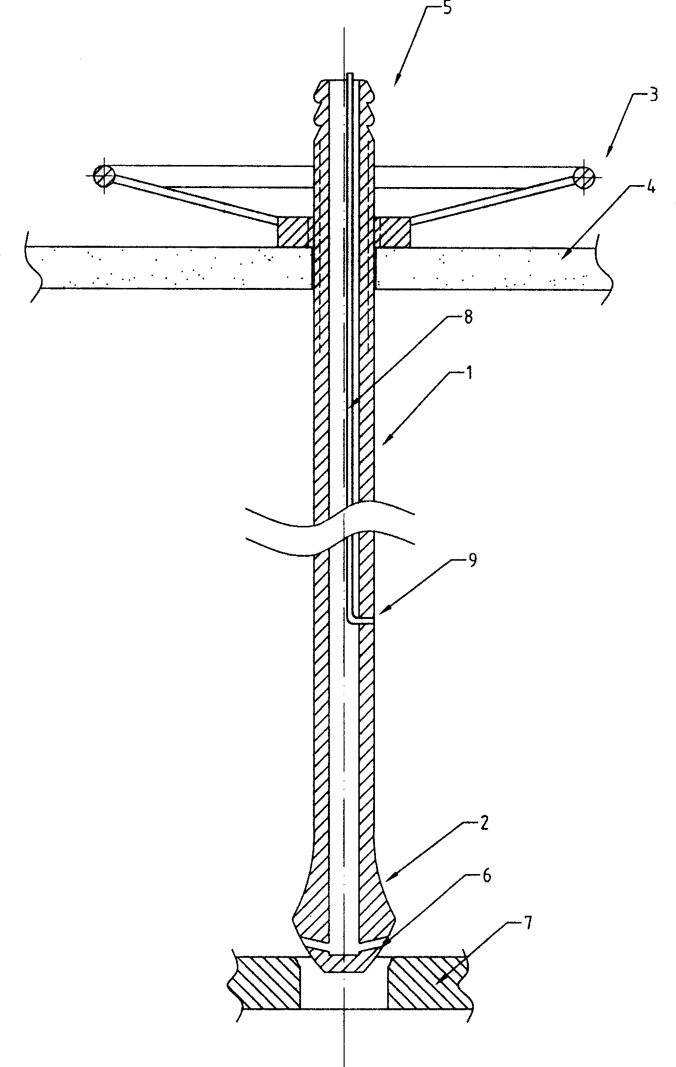
[0013] attached figure 1 Shown is a dense pool bottom valve, which is composed of a valve stem 1, a valve head 2 and a hand wheel 3. The upper end of the valve stem 1 passes through the valve seat 4 and is adjusted up and down by the hand wheel 3 through silk threads; the valve stem 1 is Hollow tubular structure, the top of the upper end is processed into a nozzle interface 5, and the lower end is connected with a hollow hammer-shaped valve head 2. The valve head 2 is directly above the valve base 7, and the valve base 7 is installed on the discharge port of the dense pool. There are four spray holes radiating in the horizontal direction around a section of the side from the cusp.
Embodiment 2
[0015] This embodiment is a dense pool bottom valve, which is composed of a valve stem 1, a valve head 2 and a hand wheel 3. The upper end of the valve stem 1 passes through the valve seat 4 and is adjusted up and down by the hand wheel 3 through silk threads; the valve stem 1 is Hollow tubular structure, the top of the upper end is processed into a nozzle interface 5, and the lower end is connected with a hollow hammer-shaped valve head 2. The valve head 2 is directly above the valve base 7, and the valve base 7 is installed on the discharge port of the dense pool. There are eight spray holes radiating toward the horizontal obliquely upward direction around a section of side from the cusp.
Embodiment 3
[0017] attached figure 2 Shown is a dense pool bottom valve, which is composed of a valve stem 1, a valve head 2 and a hand wheel 3. The upper end of the valve stem 1 passes through the valve seat 4 and is adjusted up and down by the hand wheel 3 through silk threads; the valve stem 1 is Hollow tubular structure, the top of the upper end is processed into a nozzle interface 5, and the lower end is connected with a hollow hammer-shaped valve head 2. The valve head 2 is directly above the valve base 7, and the valve base 7 is installed on the discharge port of the dense pool. There are ten spray holes radiating toward the horizontal and horizontal obliquely upwards on the side of a section away from the cusp. A small-diameter seamless steel pipe 8 is welded in the valve stem 1, and the lower end of the small-diameter seamless steel pipe 8 is connected to the injection hole 9 around the pipe wall of the valve stem.
PUM
 Abstract
Description
Claims
Application Information
 - R&D Engineer
- R&D Manager
- IP Professional
- Industry Leading Data Capabilities
- Powerful AI technology
- Patent DNA Extraction
Browse by: Latest US Patents, China's latest patents, Technical Efficacy Thesaurus, Application Domain, Technology Topic, Popular Technical Reports.
© 2024 PatSnap. All rights reserved.Legal|Privacy policy|Modern Slavery Act Transparency Statement|Sitemap|About US| Contact US: help@patsnap.com


