
Plasma display panel

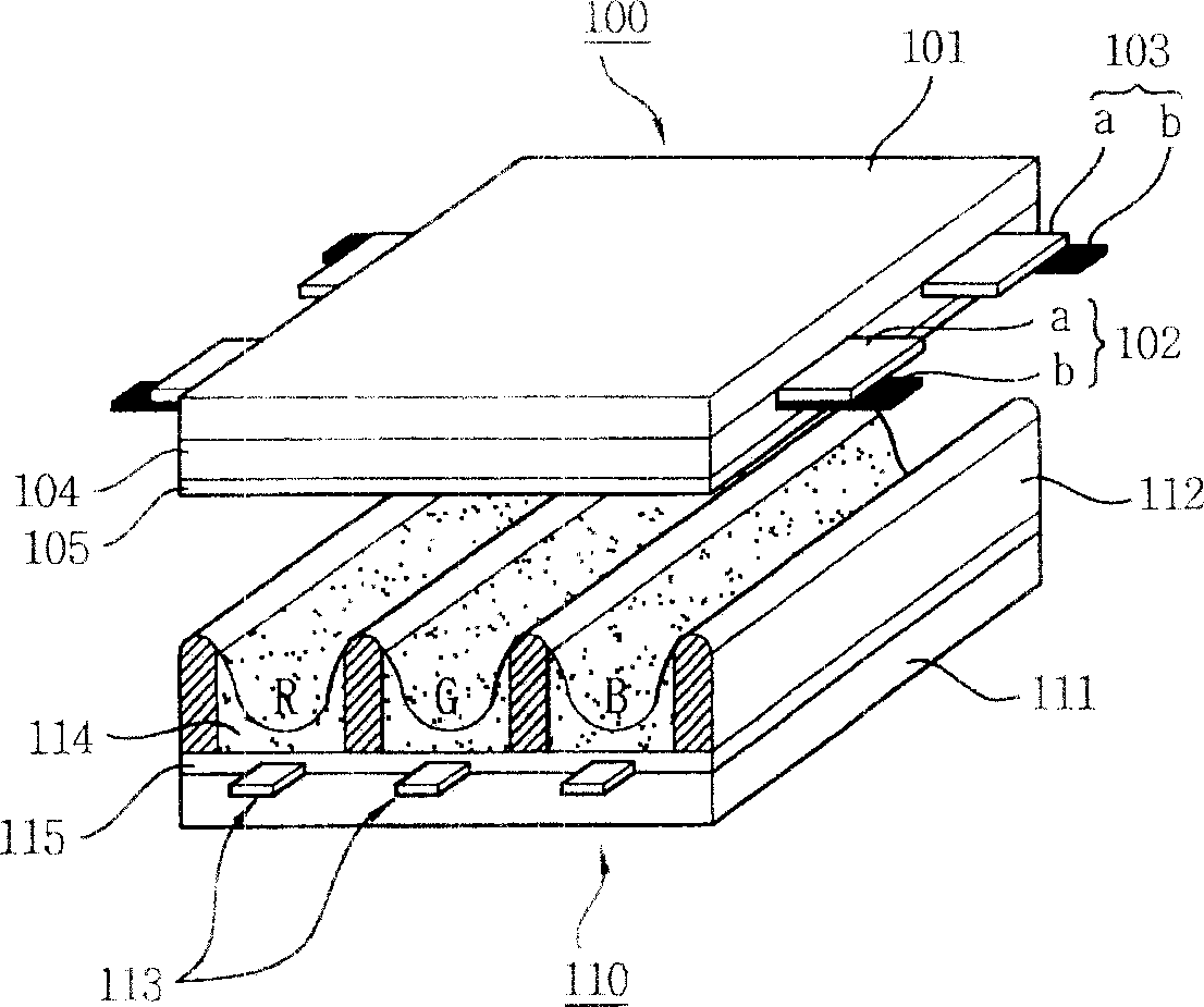
A display panel and plasma technology, applied in solid cathode components, cold cathode tubes, etc., can solve the problems of deterioration of color mixing and difficulty in arrangement of partition walls, and achieve the effects of improving color mixing, improving contrast and reducing reflectivity.

Inactive Publication Date: 2007-02-14
LG ELECTRONICS(NANJING) PLASMA CO LTD
View PDF0 Cites 0 Cited by
  • Summary
  • Abstract
  • Description
  • Claims
  • Application Information

AI Technical Summary

Problems solved by technology

[0034] At the same time, since the black matrix 300 is formed corresponding to the partition walls, there is a problem that it is difficult to align with the partition walls.
[0035] Moreover, it can be seen that the pixel color combined by the sub-pixel light emission is gradually close to the color of adjacent pixels in space, which leads to the problem that the color mixing property of the color deteriorates

Method used


Image

  • Plasma display panel
  • Plasma display panel
  • Plasma display panel

Examples


Embodiment Construction

[0063] Hereinafter, the plasma display panel of the present invention will be described in detail with reference to the drawings and embodiments.

[0064] Figure 5 is a side view of a plasma display panel according to an embodiment of the present invention.

[0065] like Figure 5 As shown, the plasma display panel consists of a front panel 500 in which a plurality of sustain electrode pairs formed by pairing scan electrodes 502 and sustain electrodes 503 are arranged on the front glass 501 of the display screen, and a plurality of sustain electrode pairs are arranged on the rear glass 511 forming the back side. The rear panel 510 of a plurality of address electrodes 513 intersecting each sustain electrode pair is formed by parallel bonding at a certain interval.

[0066] The front panel 500 includes: a scan electrode 502 and a sustain electrode 503 that make mutual discharge in a discharge cell so as to maintain the cell to emit light, that is, a transparent electrode (a) ...


PUM


Abstract

This invention discloses a plasma display panel forming a black matrix on the corresponding wall including a first baffle wall dividing sub-pixels and a second baffle wall dividing units composed of sub-pixels, the amplitude of which is wider than that of the first wall to form a black matrix corresponding its upper part, the color of the sub-pixels is red, green or blue, the unit characterizes in constituting a unit by red, green and blue sub-pixels.

Description

1. Technical field [0001] The present invention relates to a plasma display panel, in particular to a plasma display panel in which a black matrix is ​​formed corresponding to partition walls. 2. Background technology [0002] Generally speaking, in a plasma display panel, the partition wall formed between the front panel and the rear panel constitutes a unit cell, and each cell is filled with neon (Ne), helium (He) or a mixed gas such as neon and helium (Ne +He) such charge and discharge gas and inert gas containing a small amount of xenon (Xe). When discharging by high-frequency voltage, the inert gas emits vacuum ultraviolet rays (Vacuum Ultraviolet rays) to make the phosphors formed between the partitions emit light and display images. like figure 1 Shown is the general structure of the plasma display panel. [0003] figure 1 It is a side view of the structure of a general plasma display panel. [0004] like figure 1 As shown, the plasma display panel is composed o...

Claims


Application Information

Patent Timeline
Patent Type & Authority Applications(China)
IPC IPC(8): H01J17/02H01J17/04H01J17/16H01J17/49
Inventor 朴宰範閔雄基
Owner LG ELECTRONICS(NANJING) PLASMA CO LTD
Learn More