
Supercharger with electric motor

A supercharger and electric motor technology, which is applied in the direction of electric components, engine components, combustion engines, etc., can solve the problems of increased vehicle weight, large-scale equipment, narrowed flow path, etc., to improve compression efficiency and reliability , Cooling system simplification, effect of suppressing weight increase

Active Publication Date: 2007-02-14
IHI CORP
View PDF2 Cites 14 Cited by
  • Summary
  • Abstract
  • Description
  • Claims
  • Application Information

AI Technical Summary

Problems solved by technology

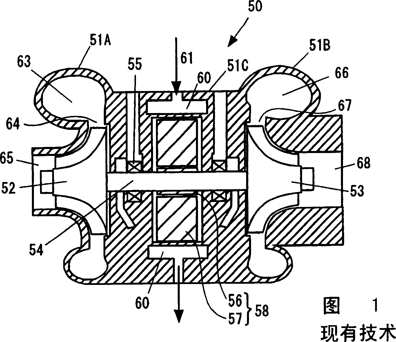
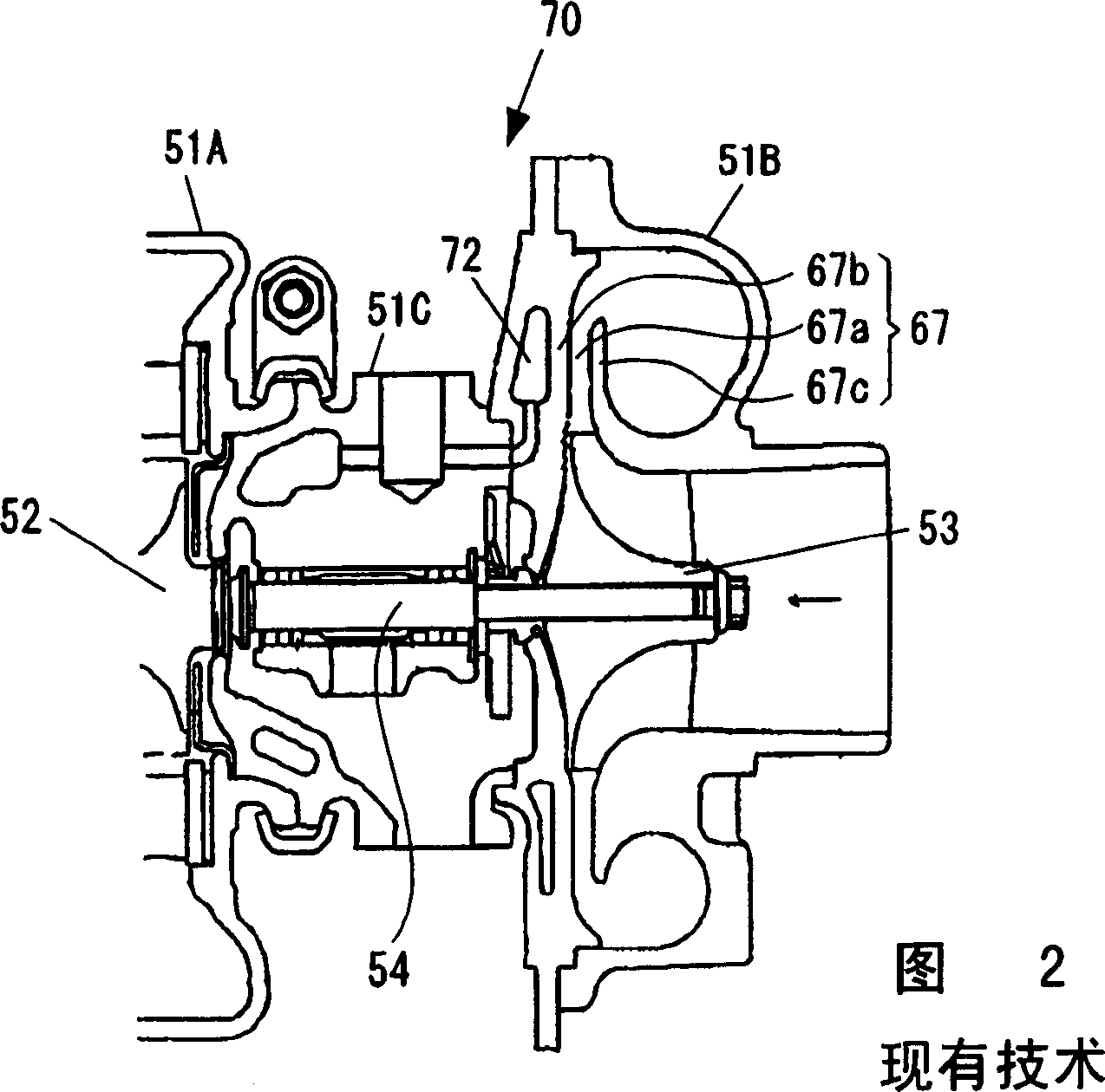
Therefore, in a supercharger with an electric motor, the oil mist solidifies and accumulates in the diffuser portion, and the solidified and deposited carbonized layer narrows the flow path of the diffuser portion 67 and increases the flow path resistance. The problem of reduced compression efficiency of the compressor still exists
[0013] In addition, although it is conceivable to provide a cooling structure (cooling passage 72) similar to that of the above-mentioned Patent Document 2 in the supercharger with an electric motor to prevent the oil mist from solidifying and accumulating in the diffuser portion 67, the addition of the electric motor in Patent Document 1 In the case where the cooling passage 72 similar to that in Patent Document 2 is provided in the press 50, it is necessary to separately provide the cooling liquid flow passage 60 and the cooling passage.
Therefore, there is a problem that the structure is complicated, the weight is increased, the device is enlarged, the cost is increased, and the mountability of the vehicle is affected, which increases the weight of the vehicle.

Method used


Image

  • Supercharger with electric motor
  • Supercharger with electric motor
  • Supercharger with electric motor

Examples


Embodiment Construction

[0024] Hereinafter, preferred embodiments of the present invention will be described in detail with reference to the drawings. In addition, the same code|symbol is attached|subjected to the common part in each drawing, and repeated description is abbreviate|omitted.

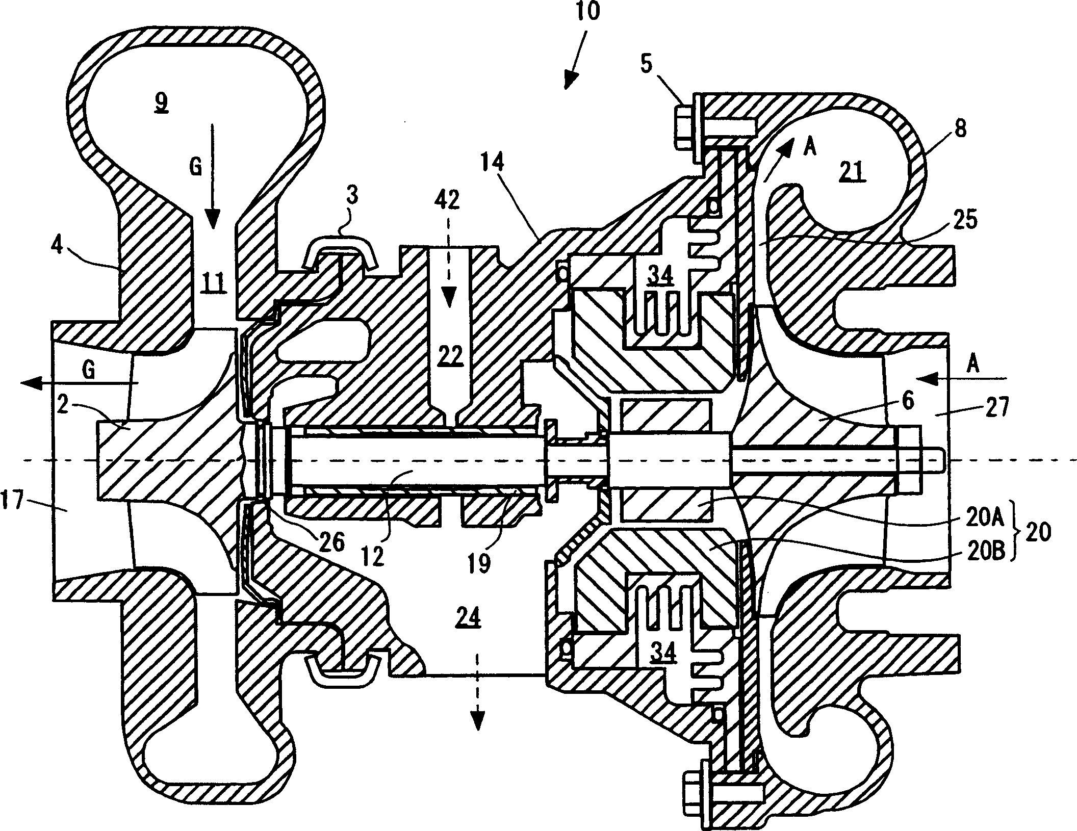
[0025] image 3 It is a cross-sectional view of a supercharger with an electric motor according to an embodiment of the present invention. Such as image 3 As shown, this supercharger 10 with electric motor includes: turbine impeller 2; turbine housing 4; rotating shaft 12; compressor impeller 6; compressor housing 8;

[0026] Arranged on the exhaust passage side are a turbine impeller 2 that is rotationally driven by exhaust gas G of the internal combustion engine, and a turbine housing 4 that surrounds the turbine impeller 2 . The turbine housing 4 has a swirl chamber 9 formed around the turbine wheel 2 , and the swirl chamber 9 communicates with the turbine wheel 2 via an annular gas flow path 11 . In additi...


PUM


Abstract

In a supercharger (10) with an electric motor in accordance with the present invention, the electric motor (20) is arranged at a position adjacent to a compressor impeller (6), a center housing (14) has a cooling fluid flow path (34) formed in such a manner as to surround the electric motor (20) and be adjacent to a diffuser portion (25). A first cooling structure portion (38) is formed at a position in the electric motor (20) side in the cooling fluid flow path (34), a second cooling structure portion(39) is formed at a position in the diffuser portion (25) side in the cooling fluid flow path (34). The electric motor (20) is cooled by the first cooling structure portion (38). The diffuser portion (25) is cooled by the second cooling structure portion (39).

Description

technical field [0001] The present invention relates to a supercharger with an electric motor, which is driven by the exhaust gas of an internal combustion engine and compresses intake air for supercharging, and which has a rotationally driven electric motor for an auxiliary compressor. Background technique [0002] In order to improve the performance of the internal combustion engine, a supercharger (also called a turbocharger), which is driven by the exhaust gas of the internal combustion engine and presses the intake air to perform supercharging (also called a turbocharger), has been widely used. In addition, a supercharger with an electric motor is widely used, that is, an electric motor is incorporated coaxially with the rotating shaft of the supercharger, and the acceleration responsiveness is improved by assisting the rotational driving of the supercharger by acceleration, and the like. [0003] Patent Document 1 below discloses a prior art related to a supercharger w...

Claims


Application Information

Patent Timeline
Patent Type & Authority Applications(China)
IPC IPC(8): F02B37/10F02B39/00F02B39/10F02B39/16H02K9/19
CPCF02B39/10F02B37/10F02B39/14F05D2220/40H02K7/14F05B2220/40F02C7/275F02B37/14Y02T10/144F01D25/125F02B39/005Y02T10/12
Inventor 涩井康行清水政宏
Owner IHI CORP
Learn More