Clamping device, substrate transmitting device, and on-line fpd automatic optical detection device

A technology of clamping device and transmission device, which is applied in the direction of nonlinear optics, optics, measuring devices, etc., and can solve problems such as substrate scratches

Inactive Publication Date: 2007-02-07
优视株式会社
View PDF0 Cites 20 Cited by
  • Summary
  • Abstract
  • Description
  • Claims
  • Application Information

AI Technical Summary

Problems solved by technology

[0005] However, recently, with the rapid development of large-sized substrates and their high-speed transmission, when the conventional clamping device 700 fixes the substrate 500 using the mechanical clamping force of the cylinder, its disadvantage is that, because the clamping force used to fix the substrate 500 , the substrate 500 is separated from the clamping device 700 during the transfer of the substrate
In addition, even if the substrate 500 is not completely separated, the substrate 500 slides a predetermined distance from the position where the clamping device 700 is fixed, thereby causing scratches on the substrate.

Method used


Image

  • Clamping device, substrate transmitting device, and on-line fpd automatic optical detection device
  • Clamping device, substrate transmitting device, and on-line fpd automatic optical detection device
  • Clamping device, substrate transmitting device, and on-line fpd automatic optical detection device

Examples


Embodiment Construction

[0044] Hereinafter, preferred embodiments of the present invention will be described in detail with reference to the accompanying drawings.

[0045] The upper and lower chucks capable of suctioning the substrate with vacuum will be explained in more detail below.

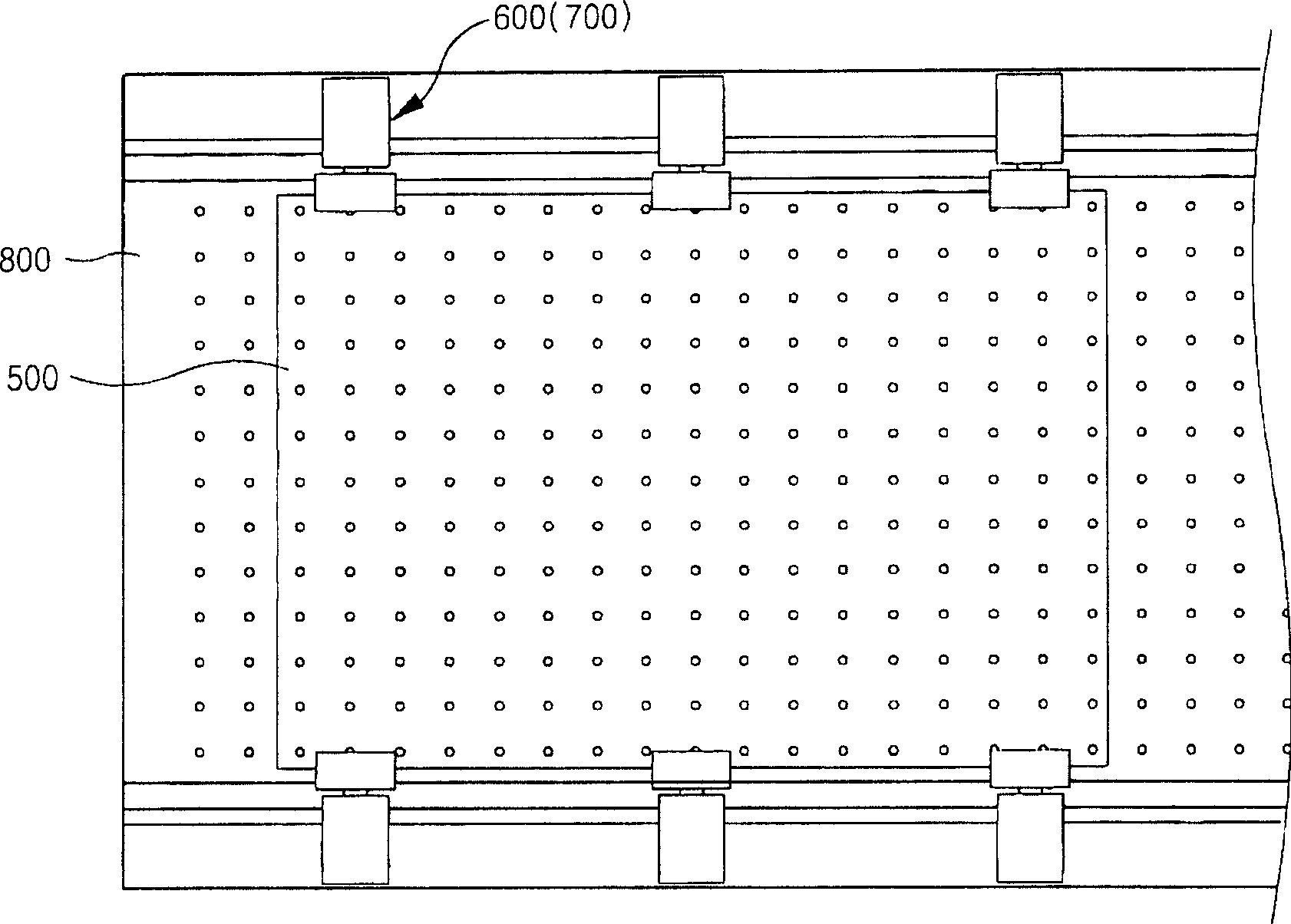
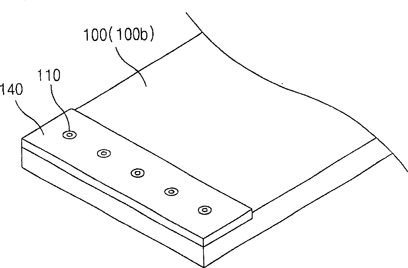
[0046] Such as Figures 3a to 5 As shown, the fixing unit 100 for fixing a substrate includes an upper chuck 100a and a lower chuck 100b. A suction nozzle 110 for sucking and fixing the substrate 500 is formed on at least one of opposing surfaces of the upper chuck 100 a and the lower chuck 100 b facing each other. In other words, at least one of the opposite surfaces is provided with a through hole 150 passing through the upper chuck 100a and the lower chuck 100b. The suction nozzle 110 is disposed in the through hole 150 . At this time, the suction nozzle 110 may be formed on one or both opposing surfaces of the upper chuck 100a and the lower chuck 100b. If the suction nozzles 110 are formed on two opposite su...


PUM

PropertyMeasurementUnit
thicknessaaaaaaaaaa

Abstract

The present invention discloses a substrate clamping device and substrate transmitting device, used for mechanically fixing one side of the substrate and transferring the substrate through vac sorb. The substrate clamping device includes: a upper chuck; a lower chuck, wherein the structure is to put in and clamp the substrate between the upper chuck and the lower chuck; and a vacuum nozzle, to construct to adsorb and fixing the substrate on at least one of the upper chuck and the lower chuck opposite each other, so the substrate fixed by the substrate clamping device is separated during the transport process or scratched on the contact surface are prevented. When the substrate clamped by the substrate clamping device transmits rapidly, the invention prevents the substrate and the substrate clamping device separate and so assure the reliability of the substrate transmitting and advances the productivity of the product.

Description

technical field [0001] The present invention relates to a clamping device, a substrate transfer device, and an in-line automatic optical inspection device for flat panel displays, and more particularly to a substrate that can be prevented from being separated or its position fixed by increasing the clamping force used to transfer the substrate Changing clamping devices, substrate transfer devices, and in-line automatic optical inspection devices for flat panel displays. Background technique [0002] During the manufacturing process of a flat panel display (FPD), scratches or various defects may be formed on a substrate. Use display panel inspection equipment to detect scratches or various defects to reduce the defective rate. For example, when guiding a display substrate such as a TFT-LCD substrate, PDP or color filter, an image of the object being inspected is captured using an optical lens and a CCD camera, after which an online FPD automatic optical inspection device can...

Claims


Application Information

Patent Timeline
Patent Type & Authority Applications(China)
IPC IPC(8): H01L21/683H01L21/677H01L21/66B65G49/05B65G47/91G01N21/956
CPCB65G47/911B65G2249/04G02F1/1303G02F1/1309H01J9/42
Inventor 金玟锡金相银李英成李恩璟闵相植
Owner 优视株式会社
Why Eureka
Try Eureka