
Plane inverse F type antenna and its producing method

一种制作方法、天线的技术,应用在天线、谐振天线、电气短天线等方向,能够解决结构复杂、所占空间大、不适应天线小型化发展等问题,达到有利于工业化生产、节省成本的效果

Inactive Publication Date: 2007-01-24
FOXCONN (KUNSHAN) COMPUTER CONNECTOR CO LTD +1
View PDF1 Cites 10 Cited by
  • Summary
  • Abstract
  • Description
  • Claims
  • Application Information

AI Technical Summary

Problems solved by technology

However, the above-mentioned inverted F antenna adopts a three-dimensional structure, and the radiating part, the short circuit board and the ground plane are located in different planes, and the structure is complex and occupies a large space, which is not conducive to industrial production and cost saving, and does not adapt to the trend of antenna miniaturization.

Method used


Image

  • Plane inverse F type antenna and its producing method
  • Plane inverse F type antenna and its producing method
  • Plane inverse F type antenna and its producing method

Examples


Embodiment Construction

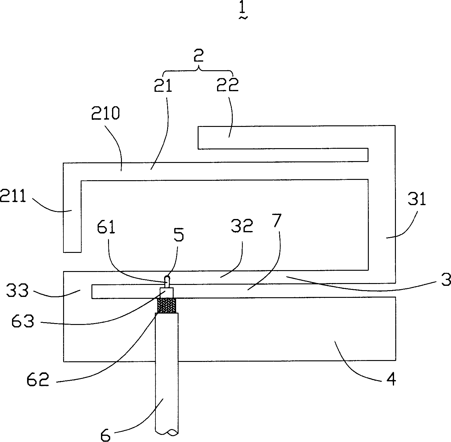
[0017] see figure 1 As shown, the planar inverted-F antenna 1 of the present invention is assembled in an electronic device for receiving or transmitting signals. In this embodiment, the electronic device is a notebook computer (not shown). The planar inverted-F antenna 1 includes a radiation part 2 , a ground part 4 and a connection part 3 connecting the radiation part 2 and the ground part 4 .

[0018] The radiating part 2 includes a first radiating part 21 and a strip-shaped second radiating part 22 extending horizontally along the first direction, wherein the first radiating part 21 is a low frequency radiating part, and the second radiating part 22 is a high frequency radiating part. The first radiating part 21 is L-shaped, which includes a first part 210 extending along the first direction parallel to the second radiating part 22 and extending along the second direction perpendicular to the first part 210 from the end of the first part 210 toward the grounding part 4. T...


PUM


Abstract

This invention relates to an inverse-F antenna and its preparation method, in which, the antenna includes a radiation part, an earth part and a connecting part connecting them, the radiation frequency is at the bands of 900MHz and 1800MHz, the processing method includes: 1, selecting a rectangular metal plate, 2, determining the length of the antenna radiation part according to the working bands 900 and 1800MHz of the antenna, 3, determining the height and shape of the connecting part based on the impedance match necessary for the antenna, 4, opening recesses on the metal plate based on said computing result to get a radiation part, a connecting part and an earth part based on the computed result, 5, determining feeding points based on impedance match and providing feed lines electrically connected at the feed points.

Description

[0001] 【Technical field to which the invention belongs】 [0002] The invention relates to an antenna and a manufacturing method thereof, in particular to a planar inverted-F antenna applied to a movable electronic device and a manufacturing method thereof. 【Background technique】 [0003] With the rapid development of modern communication technologies, more and more mobile electronic devices such as notebook computers are equipped with antennas so that they can access a wireless local area network (WLAN) to work. At present, wireless local area networks are mostly based on Bluetooth (Bluetooth) technology standards or IEEE802.11 series standards. The working frequency band of the antenna in the Bluetooth technology standard falls on 2.4GHz, and the working frequency band of the antenna in the IEEE802.11 series technical standards falls on 2.4GHz and 5GHz respectively. Therefore, most of the antennas in notebook computers are antennas applied to the above-mentioned frequency ba...

Claims


Application Information

Patent Timeline
Patent Type & Authority Applications(China)
IPC IPC(8): H01Q1/38H01Q13/08
CPCH01Q1/243H01Q9/0421H01Q5/371H01Q9/42H01Q1/2216H01Q5/0058
Inventor 谷柏冈戴隆盛洪振达柯云龙黄耀先
Owner FOXCONN (KUNSHAN) COMPUTER CONNECTOR CO LTD
Learn More