Suction device and electric dust collector therewith

A technology for inhalation appliances and vacuum cleaners, applied in the fields of suction appliances and electric vacuum cleaners, can solve problems such as unsanitary usability, poor usability, and difficulty in use, and achieve the effects of excellent usability, improved tightness, and excellent usability.

Inactive Publication Date: 2007-01-24
PANASONIC CORP
View PDF2 Cites 4 Cited by
  • Summary
  • Abstract
  • Description
  • Claims
  • Application Information

AI Technical Summary

Problems solved by technology

In addition, if the inhalation device is not installed in the correct position relative to the front duct, there is a disadvantage that it is difficult to use because the suction port of the inhalation device faces an unintended direction
Ease of positioning becomes an issue
In addition, when removing from the front-end duct, it is necessary to hold the inhalation device from the front-end duct, remove the inhalation device, or rotate it to store it in a storage position, and install the extension tube on the front-end duct, and there are the following problems: That is, it is unhygienic to have to hold the inhalation device that is prone to contamination when replacing the inhalation device and the extension tube, and it is necessary to attach and detach the inhalation device and the extension tube, and attach and detach the inhalation device from the storage part. Difference
In addition, there is the following problem: the angle of the suction port of the inhalation device is fixed, and even if the suction port of the inhalation device is movable, the angle needs to be adjusted by hand, which is unhygienic and usable after all.
[0008] As other existing structures, the inhalation device can be stored by rotating or sliding at the front end of the front end conduit, etc., and the positioning of the connection of the inhalation device with respect to the front end conduit is improved. However, after all, there is the following problem: It is not hygienic to have to hold the inhalation device that is prone to contamination when replacing the device and extension tube, and it requires three actions: attaching and detaching the inhalation device and extension tube, and attaching and detaching the inhalation device from the storage part, which deteriorates usability

Method used


Image

  • Suction device and electric dust collector therewith
  • Suction device and electric dust collector therewith
  • Suction device and electric dust collector therewith

Examples


no. 1 approach

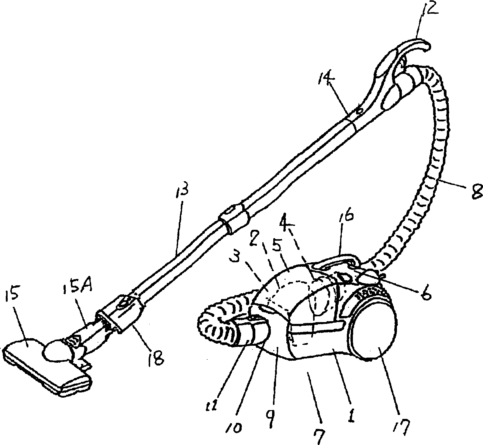
[0045] 1 is the lower part of the main body, which has a dust collection chamber 3 equipped with a dust collection bag 2 for accumulating dust on the front side, and has a dust suction motor 4 at the rear, and forms a collection chamber 5 with a cover 5 covering the dust collection bag 2 at the front. Dust chamber 3, and with main body upper part 6 covering is arranged with the top of rear motor 4 etc., and constitutes electric vacuum cleaner main body (hereinafter referred to as main body) 7. 8 is flexible pipe, and its one end is formed in main body 7 front parts The dust collection chamber 3 communicates, has a connecting duct 11, and forms an operating handle 12 to be held at the other end while in use, and serves as a front end duct 14 having a second connecting pipe connected to the extension pipe 13 as the first connecting pipe. The connecting pipe 11 is connected to the suction port 10 of the suction port 9 of the front cover 9 forming a passage for suction by the attra...

Embodiment approach 2

[0056] use Figure 7 A second embodiment of the present invention will be described.

[0057] In addition, the same code|symbol is attached|subjected to the same member as 1st Embodiment, and the description is abbreviate|omitted.

[0058] Reference numeral 49 serves as an operation pedal provided on the release mechanism operating portion of the suction device pipe 15A of the floor suction device 15 . In addition, 50 is a male terminal, which is connected to a power cord provided with a power source for supplying power to the floor suction device 15 of a drive motor (not shown) that drives a rotating brush (not shown). .

[0059] The effect of the above structure is as follows.

[0060] From the state where the floor suction device 15 is used by connecting the suction device pipe 15A to the front end of the extension pipe 13 , when using the suction device 18 , the operation pedal 49 can be pedaled and used as the suction device 18 directly. That is to say, through the en...

no. 3 approach

[0063] In addition, the same code|symbol is attached|subjected to the same aspect as 1st, 2nd embodiment, and description is abbreviate|omitted.

[0064] Reference numeral 51 denotes an operation lever, which is provided near the handle 12 of the front end 14 as a release mechanism operation unit linked to a release mechanism for releasing the connection between the floor suction device 15 and the extension pipe 13 .

[0065] The effect of the above structure is as follows.

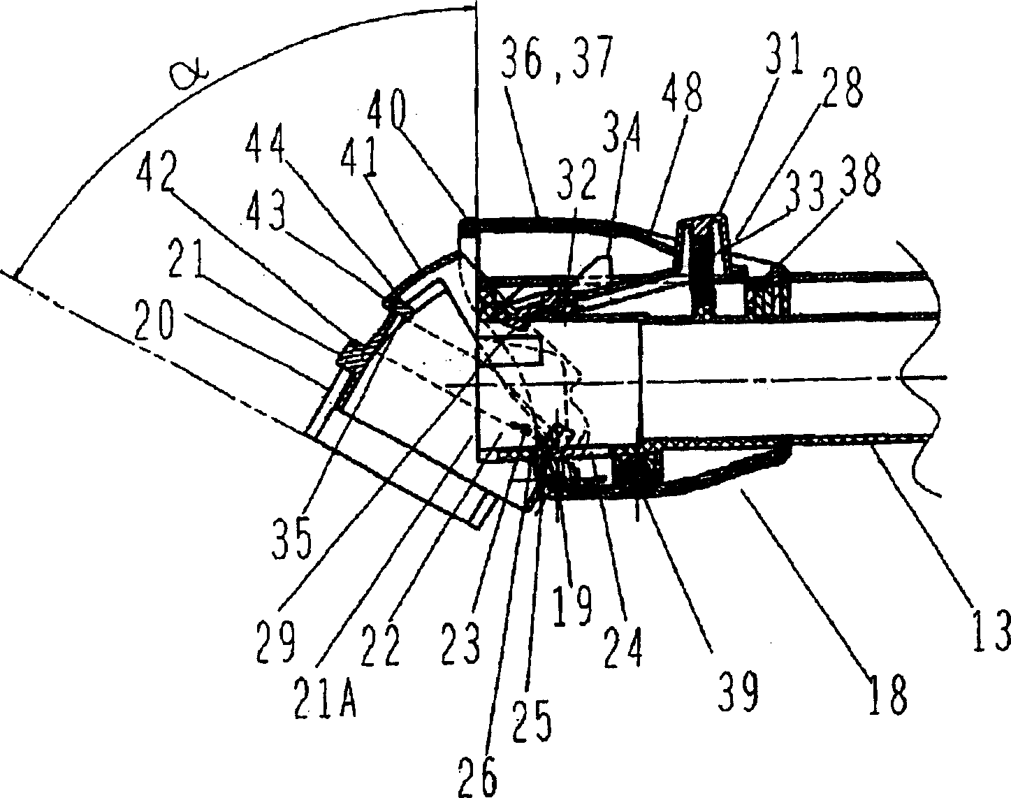
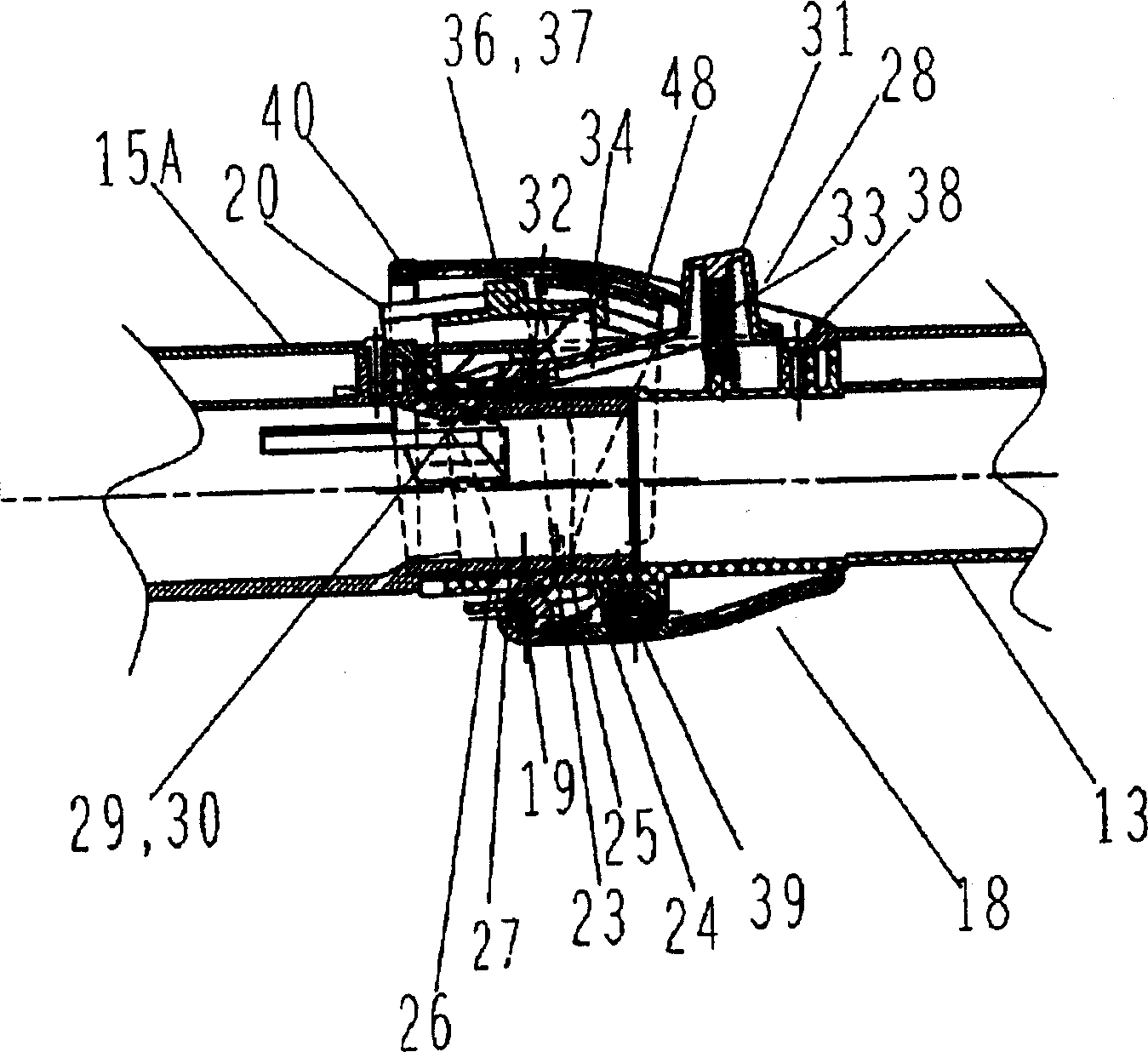
[0066] From the state where the floor suction device 15 is used by connecting the suction device pipe 15A to the front end of the extension pipe 13, when using the suction device 18, the operation lever 51 can be operated with the fingers holding the handle, and can be directly used as the suction device 18. That is to say, through the engaged part A34 of the brush holder 21 of the inhalation tool 18 and the engaging part 35 of the clip 28 are disengaged, the brush holder 21 above the extension pipe 13 is...


PUM


Abstract

The invention provides a sanitary and convenient suction nozzle allowing a user to store the suction nozzle as the extension of cleaning without touching the suction nozzle when the suction nozzle is attached / detached. The suction nozzle has a brush holder 21 which is pivotally supported to the distal end of the lower part of an extension pipe 13 in such a way a rotatable. The brush holder 21 is structured to be rotatable between a position above the outer shell of the extension pipe 13 and a position at a given angle by a hook spring 23 to energize the brush holder in the direction through a connection port 22 of the extension pipe 13, a stopper A25 formed in the brush holder 21 retractable by the rotation from a hole 24 formed in the lower part of the extension pipe 13, and a front wall 26 of the hole 24. The stopper A25, retractable from the hole 24 by the rotation when the stopper A25 abuts to a connected port 27 of a suction nozzle pipe 15A of the floor suction nozzle 15, is formed in the brush holder 21. The brush holder 21 is rotated as the stopper A25 abuts to the front wall 26 of the hole 24, and is located and held above the outer shell of the extension pipe 13.

Description

technical field [0001] The present invention relates to a suction tool used connected to a suction device such as an electric vacuum cleaner, and an electric vacuum cleaner using the same. Background technique [0002] Existing this sucking device is to have: the flexible pipe that is communicated with the dust collection room of electric vacuum cleaner, the front-end conduit that is located at the hose front end, the extension pipe that is connected on this front-end conduit, and floor suction device etc. In an electric vacuum cleaner, a brush nozzle and a gap nozzle are detachably attached to the front end nozzle and the front end of the extension pipe. As its structure, it is usually a form in which it is rotatably, slidably, and detachably connected to a mounting part provided on a front end portion of a distal guide pipe or an extension pipe (for example, refer to Patent Document 1, Patent Document 2, and Patent Document 3). , Patent Document 4). [0003] [Patent Docu...

Claims


Application Information

Patent Timeline
IPC IPC(8): A47L9/02A47L5/12
Inventor 平野章浩
Owner PANASONIC CORP
Why Eureka
Try Eureka