Acoustic boundary wave device
A technology of interface wave and sound wave, applied in the direction of electrical components, impedance network, etc., can solve the problems of increasing the cost of surface acoustic wave devices, increasing the size of surface acoustic wave devices, etc.
- Summary
- Abstract
- Description
- Claims
- Application Information
AI Technical Summary
Problems solved by technology
Method used
Image
Examples
example 1
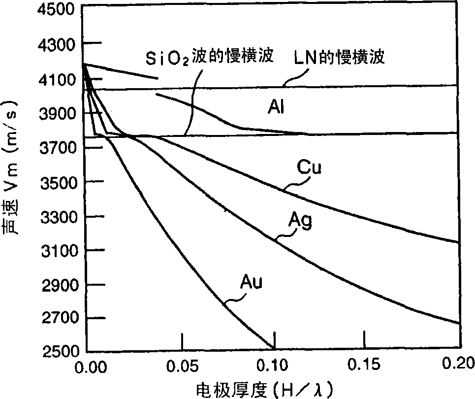
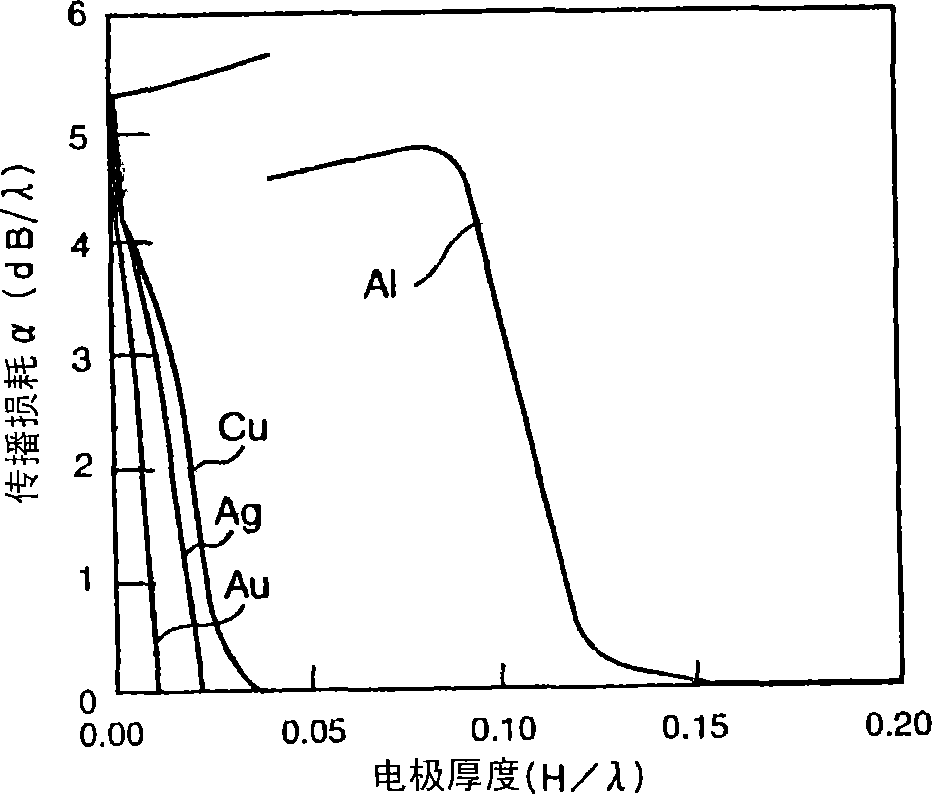
[0135] Figures 2 to 6 are shown, respectively, when using electrode materials with different densities in SiO 2 Solid-state layer and LiNbO with Euler angles (0°, 90°, 0°) 3 In the case of forming electrodes between substrates, the electrode thickness H / λ (where H represents the thickness, and λ represents the wavelength of the SH-type boundary acoustic wave) is related to the sound velocity, propagation loss α, and electromechanical coefficient k of the boundary acoustic wave. 2 (%), frequency temperature coefficient TCF (ppm / ℃) and power flow angle (PFA) relationship.
[0136] By "A method for estimating optimal cuts and propagation directions for excitation and propagation directions for excitation of piezoelectric surface waves" (J.J.Campbell and W.R.Jones, IEEE Trans.Sonics and Ultrason., Vol.SU-15(1968), P209-217) Calculated using the method disclosed in Figures 2 to 6 The results shown in .
[0137] In the case of free boundaries, the sound velocity and propagatio...
example 2
[0159] According to the results obtained in Example 1, in LiNbO with Euler angles (0°, θ, 0°) 3 An Au electrode with a thickness of 0.05λ is formed on the substrate, and a SiO electrode covering the Au electrode is formed 2 membrane. In this structure, the measured LiNbO 3 The Euler angle θ of the substrate and the sound velocity V and electromechanical coefficient k of the SH-type boundary acoustic wave and Stoneley wave 2 , Propagation loss α, frequency temperature coefficient TCF and power flow angle (PFA) relationship. Figures 9 to 11 Indicates Euler angle θ and sound velocity, electromechanical coefficient k 2 and frequency temperature coefficient TCF relationship. In the whole region of θ=0°-180°, the transmission loss α is 0dB / λ, and the power flow angle (PFA) is 0°.
[0160] exist Figures 9 to 11 Among them, U2 represents the SH-type boundary acoustic wave, and U3 represents the Stoneley wave that causes spurious signals.
[0161] as from Figure 10 It can be...
example 3
[0175] Below, each LiNbO with Euler angles (φ, 105°, 0°) and Euler angles (0°, 105°, ψ) 3 An Au electrode with a thickness of 0.06λ is formed on the substrate, and a SiO electrode covering the Au electrode is formed 2 film, forming a boundary acoustic wave device. In this case, measuring LiNbO 3 The Euler angles θ and ψ of the substrate and the sound velocity V and electromechanical coefficient k of the SH-type boundary acoustic wave (U2) and Stoneley wave (U3) 2 , Propagation loss α, frequency temperature coefficient TCF and power flow angle (PFA) relationship. Figures 14 to 17 Indicates that when using LiNbO with Euler angles (φ, 105°, 0°) 3 The results obtained when the substrate, Figures 18 to 21 Indicates that when using LiNbO with Euler angles (0°, 105°, ψ) 3 The results obtained when the substrate. In the entire region where φ is 0°-90°, the propagation loss α is 0dB / λ.
[0176] as from Figure 16 Obviously, in the range of φ is 0°-31°, the electromechanical c...
PUM
 Abstract
Description
Claims
Application Information
 - R&D Engineer
- R&D Manager
- IP Professional
- Industry Leading Data Capabilities
- Powerful AI technology
- Patent DNA Extraction
Browse by: Latest US Patents, China's latest patents, Technical Efficacy Thesaurus, Application Domain, Technology Topic, Popular Technical Reports.
© 2024 PatSnap. All rights reserved.Legal|Privacy policy|Modern Slavery Act Transparency Statement|Sitemap|About US| Contact US: help@patsnap.com


