Shock absorber for the holding assembly of a reciprocating tool

A technology of assembly and shock absorber, applied in the field of shock absorbers, which can solve the problems of high instantaneous stress and large impact load, etc.

Inactive Publication Date: 2006-12-20
CATERPILLAR INC
View PDF1 Cites 6 Cited by
  • Summary
  • Abstract
  • Description
  • Claims
  • Application Information

AI Technical Summary

Problems solved by technology

This results in very high shock loads, resulting in high transient stresses in the components that transmit the shock load back to the hammer body

Method used


Image

  • Shock absorber for the holding assembly of a reciprocating tool
  • Shock absorber for the holding assembly of a reciprocating tool
  • Shock absorber for the holding assembly of a reciprocating tool

Examples


Embodiment Construction

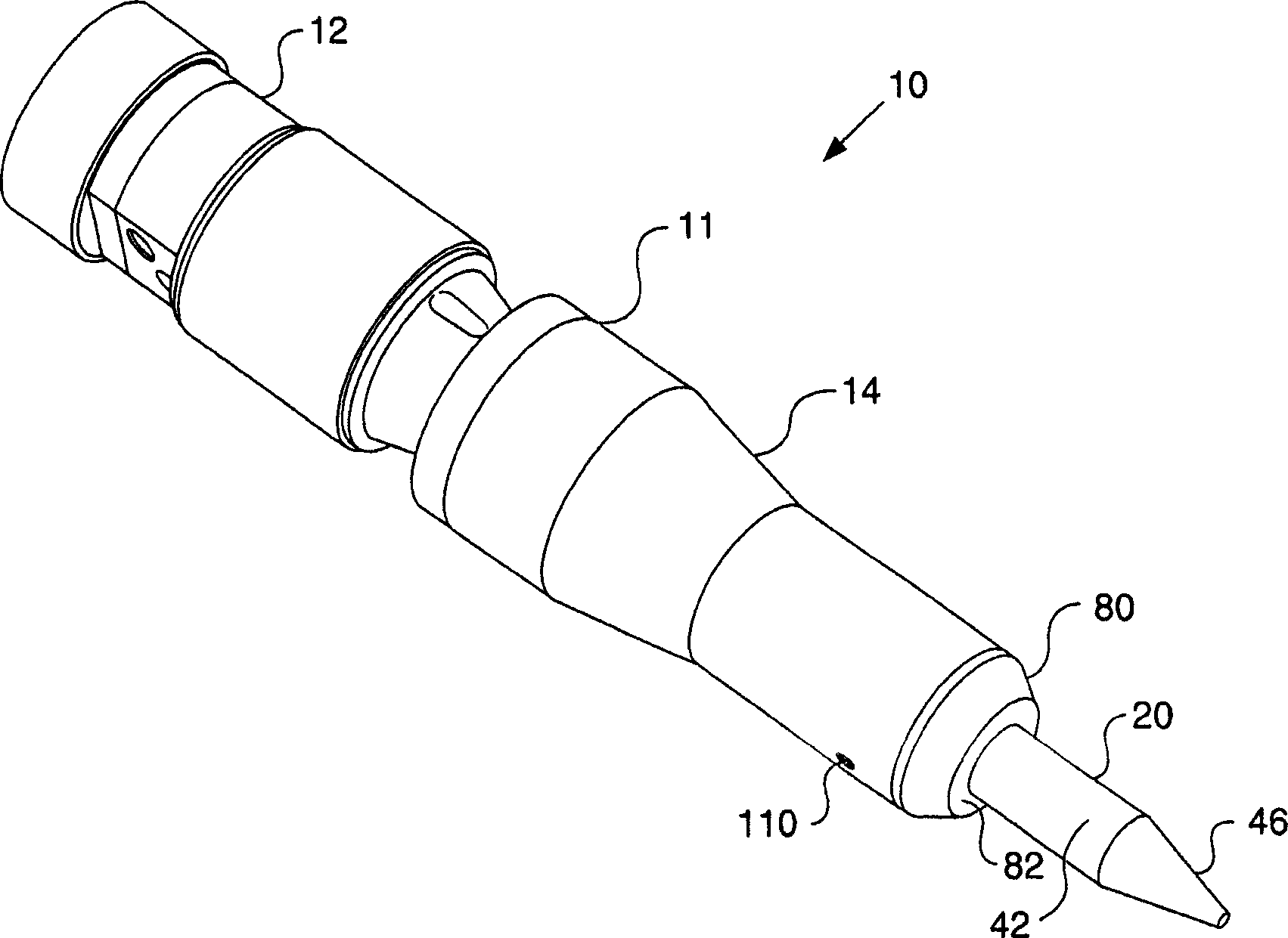
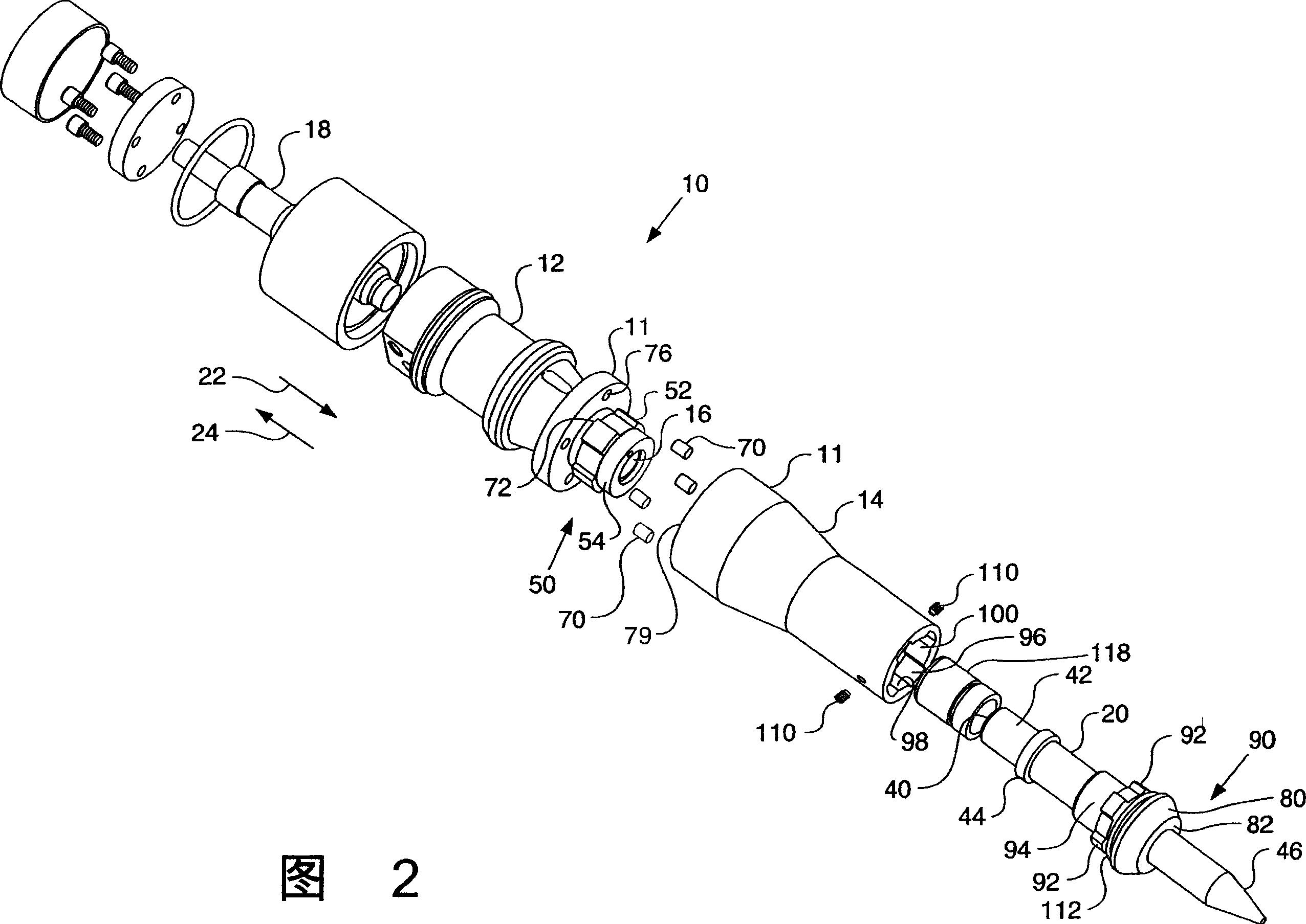
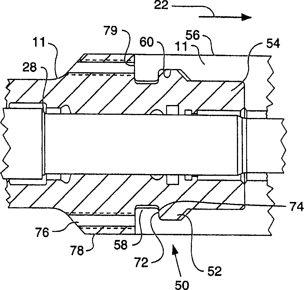
[0017] see Figure 1 to Figure 3 , which shows a tool assembly 10, in particular a hydraulic hammer tool assembly, which is connectable to a backhoe or excavator (not shown). The tool assembly 10 includes a housing 11 , a chamber 16 formed in the housing 11 , a piston 18 and a working tool 20 . The housing 11 is a two-piece housing comprising an upper housing member 12 and a lower housing member 14, which usually form an upper and a lower chamber respectively, and these two chambers together form a chamber 16, the lower housing member The housing member is often referred to as the front end shield. Piston 18 is operably received within chamber 16 such that piston 18 is translatable in the general directions of arrows 22 and 24 . Specifically, during a working stroke, the piston 18 moves in the general direction of the arrow 22 , thereby impacting the working tool 20 . Conversely, on the return stroke, the piston 18 moves in the general direction of arrow 24 .

[0018] A hy...


PUM


Abstract

A tool assembly, for example a hydraulic or pneumatic hammer assembly, comprises a housing defining a chamber, a reciprocating work tool arranged in the chamber for cyclical movement in a work stroke and a return stroke, and a tool retention member arranged to restrain the work tool at the end of the work stroke. The tool assembly includes a shock absorber arranged to absorb impact from the work tool at the end of a stroke. The shock absorber comprises an annular resilient flange, which may be cantilevered from the tool retention member to absorb impact at the end of the work stroke or may be provided on a bushing arranged to absorb impact at the end of the return stroke. The shock absorbing flange reduces the transmission of shocks into the tool assembly, thereby providing increased life for tool assembly components.

Description

technical field [0001] The present invention relates generally to an apparatus for absorbing shocks in a tool assembly having a reciprocating work tool, and more particularly to a shock absorber for a hydraulic, electric or pneumatic impact tool assembly. Background technique [0002] Hydraulic hammers are used on job sites for breaking up large hard objects prior to handling them. Hammers can be backhoe or excavator mounted, or hand-held. Typically, the hammer assembly is powered by a hydraulic or pneumatic pressure source. During a working or power stroke, higher fluid pressure is exerted on the first shoulder of the piston, thereby driving the piston in a forward direction. The piston then strikes a work tool, commonly referred to as a cutter, which is driven forward so that the working end of the work tool strikes stones, cement, asphalt or other hard objects to be broken up. [0003] During a return stroke, fluid pressure is exerted on the second shoulder of the pist...

Claims


Application Information

Patent Timeline
Patent Type & Authority Applications(China)
IPC IPC(8): B25D17/24B25D9/00B25F5/00
CPCB25D17/24B25D17/08
Inventor 潘春晖L·P·彼勒斯二世
Owner CATERPILLAR INC
Why Eureka
Try Eureka