Eureka AIR delivers breakthrough ideas for toughest innovation challenges, trusted by R&D personnel around the world.

Driver's cabin of engineering machinery

A technology of construction machinery and cab, applied in the field of cab, can solve the problems of low reliability, difficult maintenance and unreliability, and achieve the effects of good working stability, long service life and wide application range

Inactive Publication Date: 2006-12-13
SANY HEAVY MACHINERY
View PDF0 Cites 4 Cited by
  • Summary
  • Abstract
  • Description
  • Claims
  • Application Information

AI Technical Summary

Problems solved by technology

The front window is closed most of the time during normal work, so the spring is at the maximum stretch state most of the time during normal work, and the mechanical tension spring is at the maximum position of its designed working stroke for a long time, which will inevitably lead to changes in spring stiffness. Small, showing that the elastic force is gradually decreasing, and the designed elastic force cannot be reached, that is, the designed upward boosting effect cannot be achieved.
2. The spring wire rope booster mechanism cannot achieve an ideal booster effect
In this way, a limit value is added to the spring force, and the relationship between the spring force and the stroke becomes smaller and smaller with the stroke, so the mechanism cannot achieve an ideal boosting effect
3. The reliability of the spring wire rope power-assisted mechanism is low when it moves quickly
But the design of this kind of car door makes the opening and closing of the car door more dependent on the cooperation of slide rails and rollers, and general construction machinery, such as hydraulic excavators, all work in very harsh environments, dust, sand and various There are many mixed pollutants, and these pollutants can cause the unsmooth cooperation between the slide rail and the rollers, thereby greatly reducing the adaptability of the slide rail door. At the same time, the setting of the slide rail makes the originally very limited cab space more It is difficult to arrange, and has the disadvantages of short working life, unreliability, and difficult maintenance

Method used


Image

  • Driver's cabin of engineering machinery
  • Driver's cabin of engineering machinery
  • Driver's cabin of engineering machinery

Examples


Embodiment Construction

[0070] The present invention will be described in further detail below in conjunction with the accompanying drawings and specific embodiments.

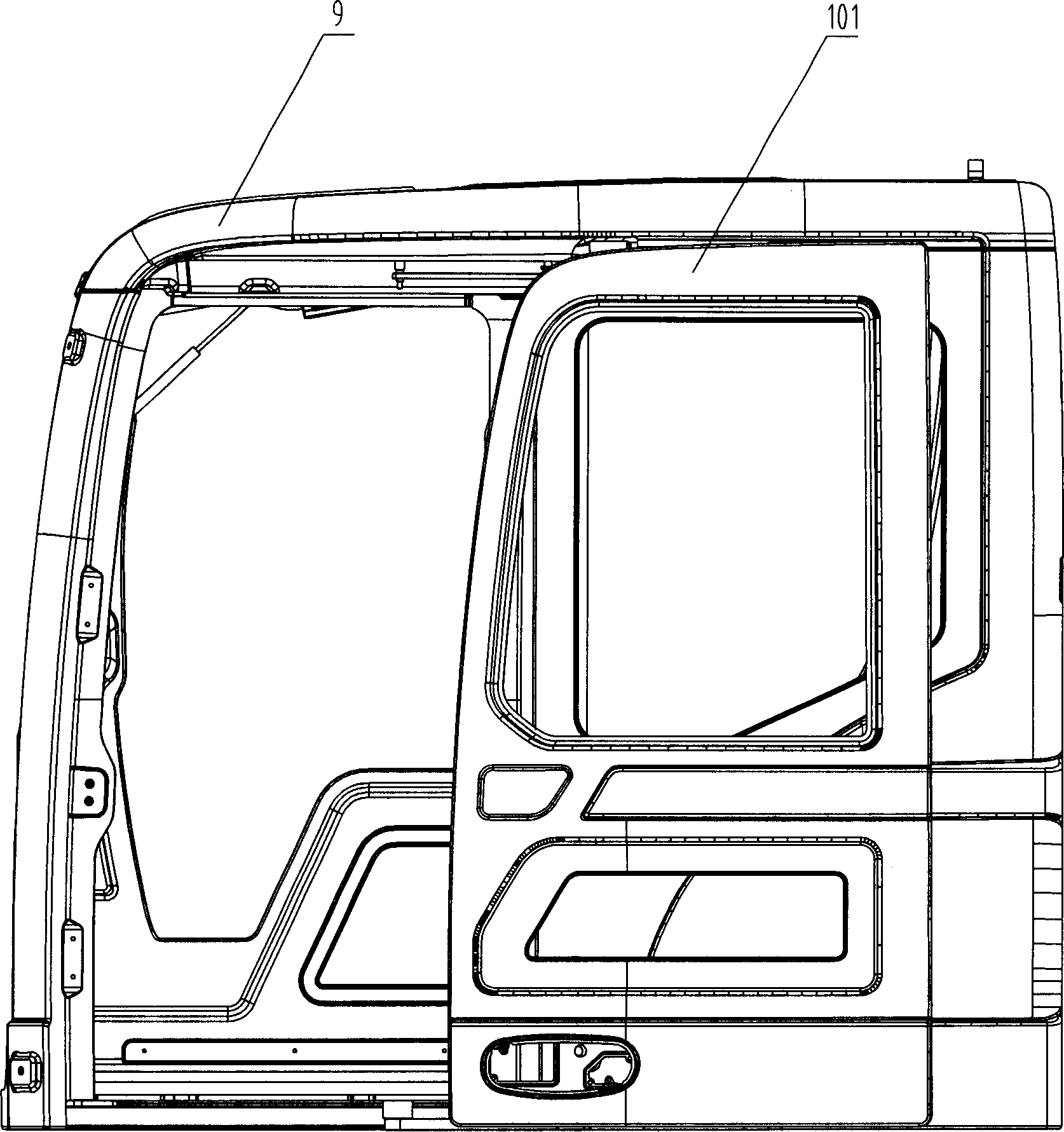
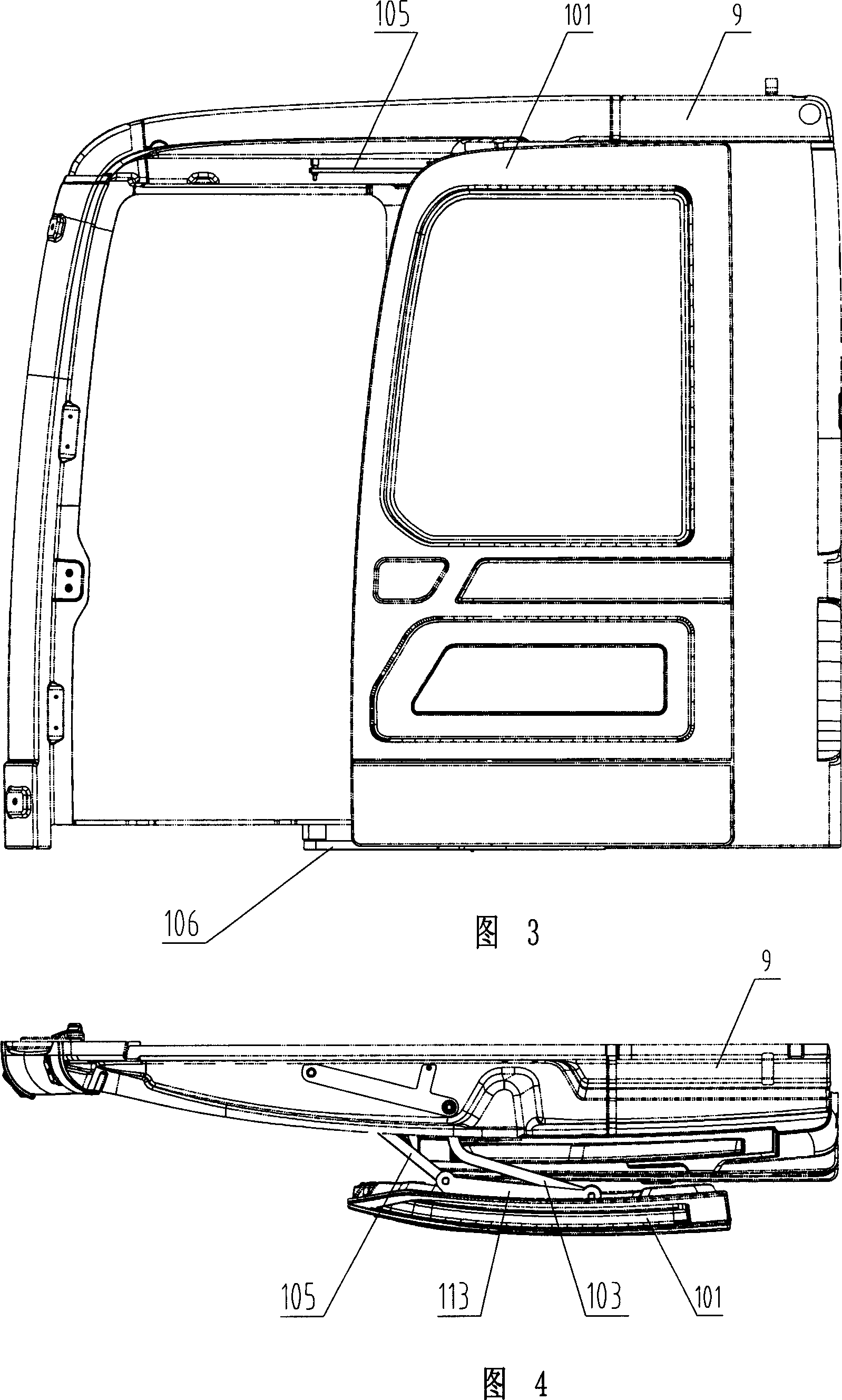
[0071] like figure 1 , figure 2 , Figure 3, Figure 4, Figure 5 and Figure 6 As shown, the cab of the engineering machinery of the present invention includes a cab body 9, a front window and a car door. The car door includes a car door body 101, and the car door body 101 is connected with an opening and closing mechanism. mechanism, the link transmission mechanism is composed of a first upper link 103 and a first lower link 104 arranged in parallel and a second upper link 105 and a second lower link 106 arranged in parallel, wherein the first upper link 103 and The first lower connecting rod 104 adopts an arc-shaped connecting rod with a large arc corner. Compared with the connecting rod that does not use a large arc corner, the large arc corner connecting rod is used. When the door is opened at the same position, the door is re...


PUM


Abstract

The invention relates to a cab of engineering machinery, which comprises a main body, a front window and a door. Wherein, said door comprises a door body connected to one switch device; said switch device comprises a rotating axle and a connecting rod transmission device; the connecting rod transmission device is formed by parallel first upper and lower connecting rods and parallel second upper and lower connecting rods; the rotating axle is fixed inside the cab; one end of first upper and lower connecting rods is connected to the rotating axle, while another end is connected to the top and bottom of vehicle door; one of second upper and lower connecting rods is connected to the main body of cab, while another end is connected to the top and bottom of vehicle door. The invention has simple structure and beautiful appearance, while it uses closed window to obtain better operation stability and easy pushing-drawing, with long service life.

Description

technical field [0001] The invention mainly relates to the field of cabs of construction machinery or walking machinery, in particular to a cab of construction machinery. Background technique [0002] In the construction machinery or walking machinery of the prior art, such as hydraulic excavators and other operating equipment with cabs are affected by factors such as stone splashes, dust, noise, wind and rain, high and low temperature, and strong ultraviolet rays in the working environment during the working process. As well as the need for personal safety protection of the driver, the driver needs to work in the cab, and because the driver needs to see the working status of the machine actuator, this type of cab should have a front window. In addition, because the driver requires opening the front window in a specific working environment to obtain a brighter visual effect than closing the front window, and even needs to extend the head, shout, and enjoy the natural wind, s...

Claims


Application Information

Patent Timeline
Patent Type & Authority Applications(China)
IPC IPC(8): E05D15/28E02F9/16
Inventor 唐修国袁颖斌
Owner SANY HEAVY MACHINERY
Why Eureka
Eureka Blog
Learn More