Selvage device

A technology of selvedge and edging, which is applied in the direction of selvage opening mechanism, textile, loom, etc., and can solve the problems of large-scale and complicated control of driving motor.

Inactive Publication Date: 2006-12-13
TSUDAKOMA KOGYO KK +1
View PDF2 Cites 7 Cited by
  • Summary
  • Abstract
  • Description
  • Claims
  • Application Information

AI Technical Summary

Problems solved by technology

Therefore, the control of the drive motor becomes more complicated, and it is necessary to use a drive motor with a higher output torque. As a result, there is a problem of increasing the size of the entire device.

Method used


Image

  • Selvage device
  • Selvage device
  • Selvage device

Examples


Embodiment Construction

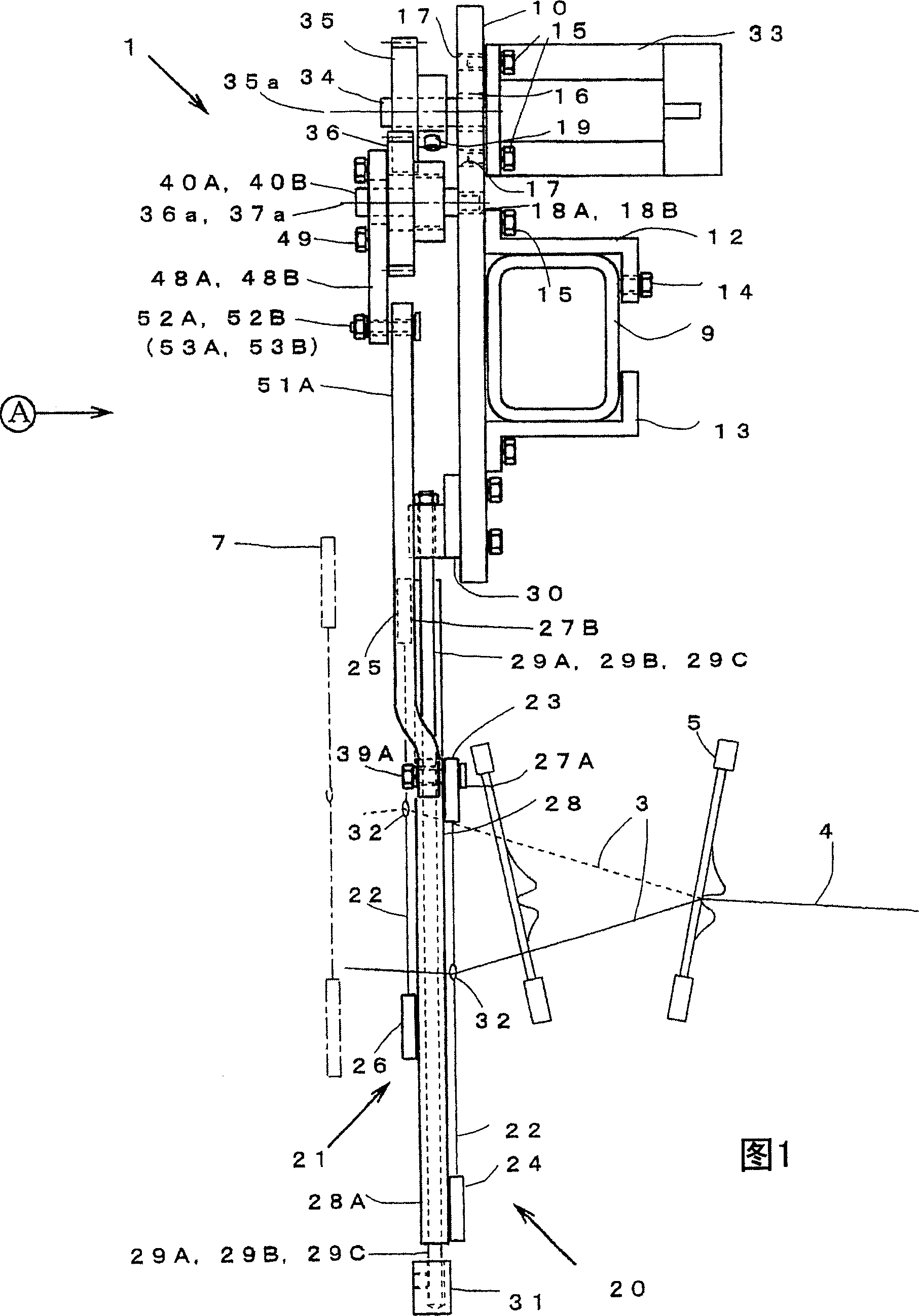
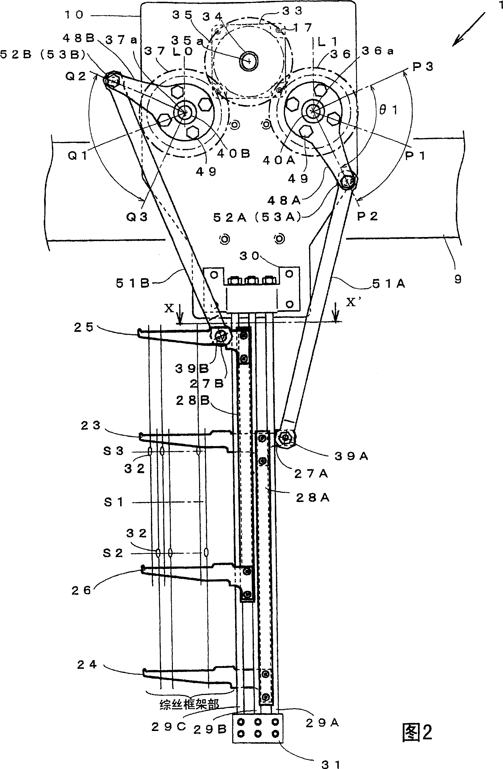
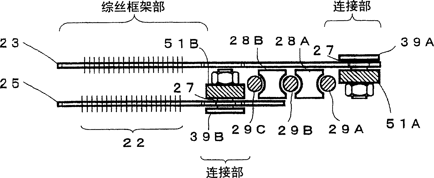
[0035] Hereinafter, specific embodiments of the selvage device for a loom according to the present invention will be described with reference to the accompanying drawings. In Figure 1~ Figure 4 In the figure above, the selvedge device 1 configured on both sides of the end of the fabric 4 to move the edge yarn 3 to open is specifically shown. The edge yarns 3, 3 are drawn out through the edge yarn bobbins, tensioners and guides, etc., which are not shown in the figure and arranged on the loom, and their front ends pass through the yarn guides 32, 32 constituting the selvage device 1 of the present invention, and then Through the reed 5 to the cloth fell and connected to the fabric 4 . In addition, in the illustration, the example of the selvedge device arranged on the right side is shown from the loom front, but the selvage device 1 not shown in figure which is bilaterally symmetrical is arrange|positioned similarly on the left side, for example.

[0036] Roughly speaking, t...


PUM


Abstract

A selvage device includes two supporters whose movements are restricted to a selvage-shedding direction and having thread guides for guiding selvage threads, a driving motor that is rotated in forward and reverse directions, and a motion-converting mechanism converting the rotation of the driving motor to reciprocating motions for the supporters. The motion-converting mechanism includes a first gear attached to an output shaft of the driving motor, a second gear meshed with the first gear and having a first pivotal connecting section at a position distant from a center of rotation of the second gear in a radial direction thereof, a second pivotal connecting section which is provided in one of the first gear and a third gear directly meshed or indirectly linked with the first gear and is positioned distant from a center of rotation of the first gear or the third gear in a radial direction thereof, and linking rods respectively provided for the two supporters, the linking rods having first ends respectively connected to the first pivotal connecting section and the second pivotal connecting section and second ends connected to the corresponding supporters.

Description

technical field [0001] The present invention relates to a selvage device that forms a selvage based on the operation of a first heald frame for hemming yarn and a second heald frame for hemming yarn that are reciprocally driven in opposite directions. Background technique [0002] Selvage devices that form a selvedge based on the operation of a first heald frame for hemming yarn and a second heald frame for hemming yarn reciprocatingly driven in opposite directions are disclosed in, for example, Patent Documents 1 to 2. [0003] The device of Patent Document 1 is a mechanism in which a two-dimensional crank mechanism is driven by an electric motor, and a pair of yarn guide members are reciprocated and linearly moved by driving the two-dimensional crank mechanism. The two-dimensional crank mechanism consists of a rod installed on the output shaft of an electric motor and a pair of connecting rods connected to both ends of the rod. A pair of links is connected one-to-one to a...

Claims


Application Information

Patent Timeline
IPC IPC(8): D03C11/00D03D47/40
CPCD03C11/00D03D47/40
Inventor 角谷和人春日久男
Owner TSUDAKOMA KOGYO KK
Why Eureka
Try Eureka