Voltage averaged allocator for charging and discharging lithium battery

A voltage averaging, lithium battery technology, applied in battery circuit devices, current collectors, electric vehicles, etc., can solve problems such as power loss

Active Publication Date: 2006-12-06
哈尔滨光宇电子有限公司
View PDF1 Cites 0 Cited by
  • Summary
  • Abstract
  • Description
  • Claims
  • Application Information

AI Technical Summary

Problems solved by technology

[0003] The present invention provides a lithium battery charging and discharging voltage average divider that does not waste the electric energy of the rechargeable battery, which overcomes the defect that the existing voltage average divider causes additional power loss

Method used


Image

  • Voltage averaged allocator for charging and discharging lithium battery
  • Voltage averaged allocator for charging and discharging lithium battery

Examples


specific Embodiment approach 1

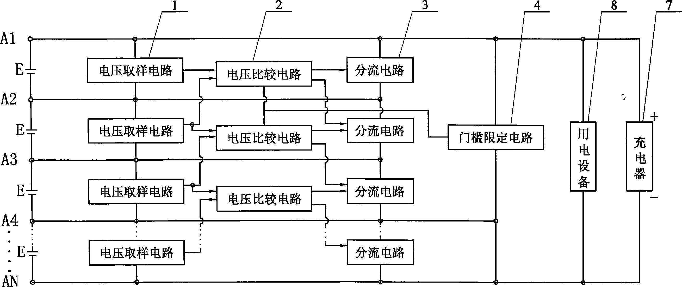
[0005] Specific implementation manner one: the following combination figure 1 This embodiment will be described in detail. This embodiment consists of N-1 voltage sampling circuits 1, N-2 voltage comparison circuits 2, N-1 shunt circuits 3, A threshold limiting circuit 4 is composed of N nodes A1, A2...AN arranged in sequence, and a voltage sampling circuit 1 and a shunt circuit 3 are connected in parallel between every two adjacent nodes. The output terminals are respectively connected to the input terminals of the two adjacent voltage comparison circuits 2 respectively, and the two output terminals of each voltage comparison circuit 2 are respectively connected to each of the controlled terminals of the two adjacent shunt circuits 3 The two shunt circuits 3 respectively correspond to the two voltage sampling circuits 1 that are input to the voltage comparison circuit 2. The threshold limiting circuit 4 is connected in parallel on the two outermost nodes of the four adjacent nod...

specific Embodiment approach 2

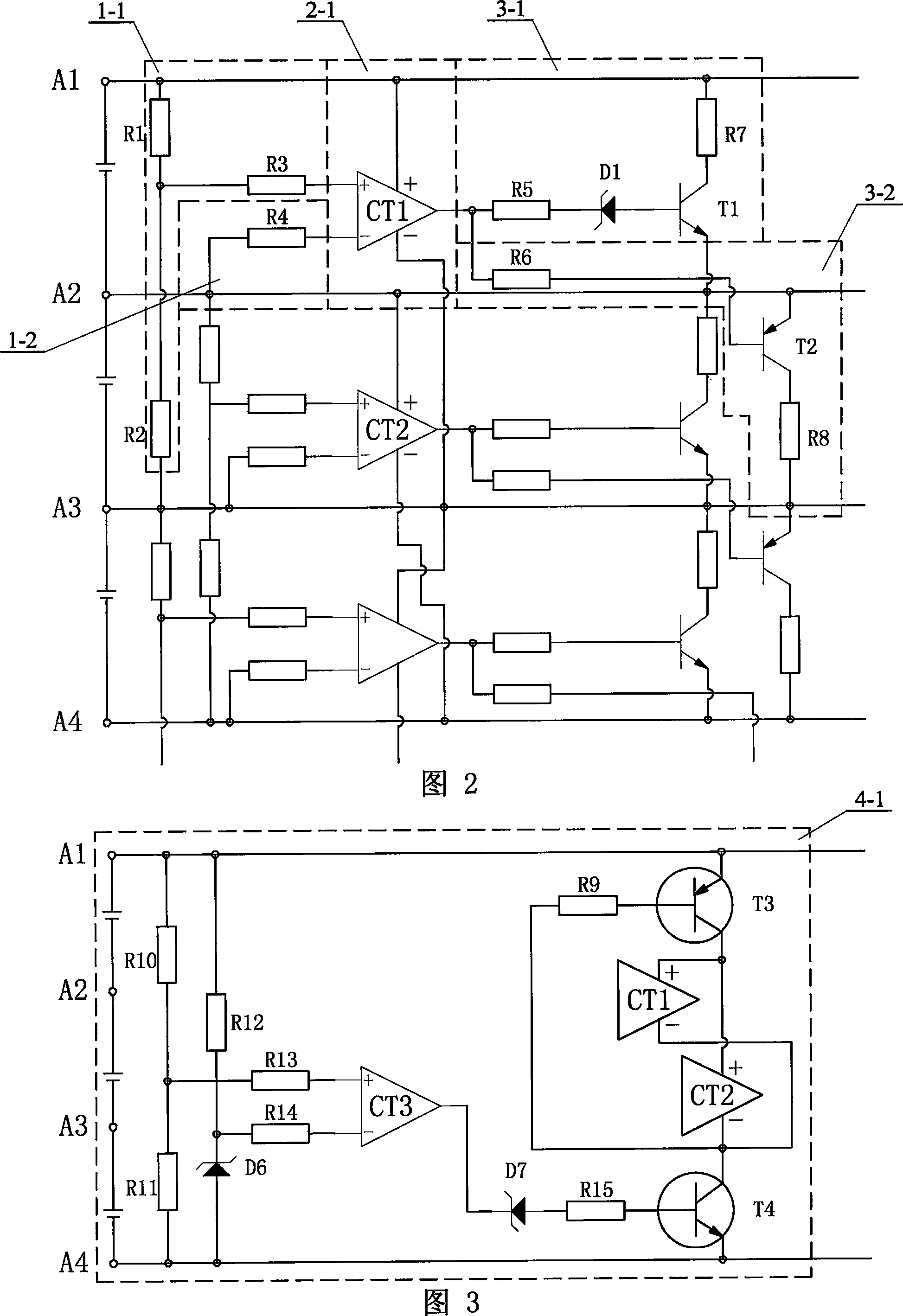
[0006] Specific implementation manner 2: The following specifically describes this implementation manner with reference to FIG. 2. The difference between this embodiment and the first embodiment is: the first voltage sampling circuit 1-1 between the first node A1 and the second node A2 is composed of a first resistor R1, a second resistor R2, and a third resistor R3. The second voltage sampling circuit 1-2 between the second node A2 and the third node A3 is composed of a fourth resistor R4, the voltage comparison circuit 2-1 is composed of a first integrated operational amplifier CT1, the first node A1 and the second node A2 The first shunt circuit 3-1 is composed of the fifth resistor R5, the seventh resistor R7, the first Zener diode D1 and the first transistor T1, and the second node A2 and the third node A3 The shunt circuit 3-2 is composed of a sixth resistor R6, an eighth resistor R8, and a second transistor T2. One end of the first resistor R1 is connected to the first node...

Embodiment approach 1

[0007] The first embodiment is the same.


PUM


Abstract

Protection circuit of charging and discharging voltage in cascaded lithium batteries is composed of N-1 pieces of voltage sampling circuit (1), N-2 pieces of voltage comparator (2), N-1 pieces of branch circuit (3), (N-1) / 4 pieces of threshold restriction circuit (4), and sequential arranged N nodes. (1) and (3) are connected to each adjacent node in parallel. Output end of each (1) is connected to each input end of adjacent two (2) respectively. Two output ends of each (2) are connected to each controlled and of adjacent two (3) respectively. The said two (3) are corresponding to two (1) of inputting signal to (2). (4) is connected in parallel to outermost two nodes in the adjacent four nodes. Output end of each (4) is connected to two controlled ends of (2) respectively. Two (2) are connected to four nodes connected to (4) I parallel. Since (4) is setup, voltage comparator is cut off when lithium batteries supply power for consumers so as not to waste energy of lithium batteries.

Description

Technical field: [0001] The invention relates to a charging and discharging voltage protection circuit for a series-connected lithium battery pack when the power supply is uninterrupted. Background technique: [0002] Lithium batteries have strict requirements on current and voltage during charging and discharging. Once exceeded, they will have serious consequences in terms of safety and life. Therefore, when lithium batteries are used in series, each group of lithium batteries requires the same parameters. Due to the cumulative error of each process in the production process of lithium batteries, various parameters of each finished lithium battery will be different, so when used in series, the voltage on each single lithium battery will be different, especially when charging , It is very easy to cause the voltage of a certain lithium battery to exceed the rated value, and in severe cases, it will cause irreversible damage and even cause safety accidents. The same is true for dis...

Claims


Application Information

Patent Timeline
IPC IPC(8): H02J7/00
Inventor 顾俊峰李桂森
Owner 哈尔滨光宇电子有限公司
Why Eureka
Try Eureka