
Surface of guiding printed substrate with micro-protuberance

A technology of substrates and micro-protrusions, applied in printing, printing plates, printing foils, etc., to achieve the effect of improving the quality of printed images, realizing the quality of printed images, and improving the quality of printed images

Inactive Publication Date: 2006-12-06
HEIDELBERGER DRUCKMASCHINEN AG
View PDF7 Cites 0 Cited by
  • Summary
  • Abstract
  • Description
  • Claims
  • Application Information

AI Technical Summary

Problems solved by technology

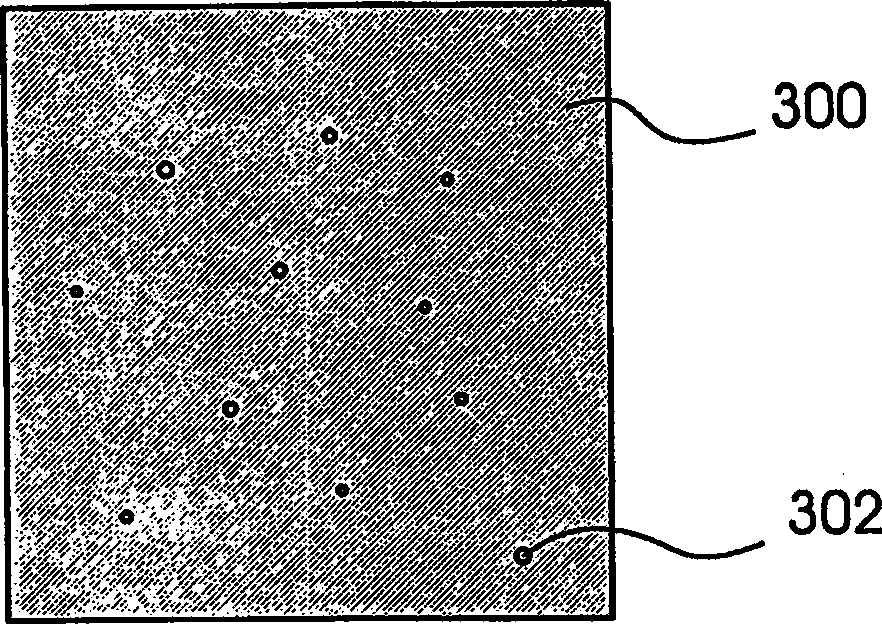
[0012] Because the solutions of the prior art do not always guarantee a satisfactory print quality, and because it is necessary to especially avoid the generation of so-called "white spots" (cf. image 3 and related instructions), so there has always been a desire to improve the surface of the leading substrate

Method used


Image

  • Surface of guiding printed substrate with micro-protuberance
  • Surface of guiding printed substrate with micro-protuberance
  • Surface of guiding printed substrate with micro-protuberance

Examples


Embodiment Construction

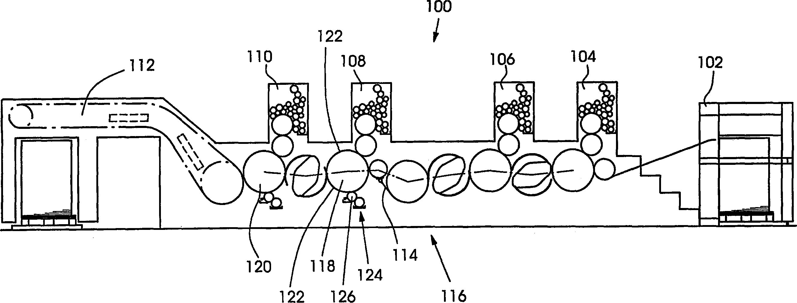
[0038] figure 1 A sheetfed offset printing press 100 is shown with a sheet feeder 102 , four offset printing units 104 , 106 , 108 and 110 and a sheet delivery 112 . The printing press 100 can be operated in a duplex printing mode, ie two first printing units 104 and 106 print the first side of a substrate sheet 114 and the other two printing units 108 and 110 print the second side of the substrate 114 Second side. For this purpose, the printing material 114 is turned over by a turning device 16 .

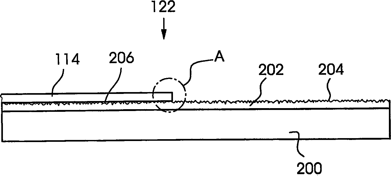
[0039] The printing material 114 rests with the printed first side against the two impression cylinders 118 and 120 arranged downstream of the inversion device 116 and passes through the corresponding printing gaps of the printing devices 108 and 110 under pressing force. In order to prevent ink from falling off and accumulating on the respective substrate-guiding surfaces of the impression cylinders 118 and 120 and to prevent relative movement between the substrate 114 and the ...


PUM


Abstract

A printing-material-carrying surface, having micro-elevations which make contact with a printing material provided with printing ink, and having a guide printing is at least partly provided, preferably substantially only at peaks of the micro-elevations, with a fluid additive to improve print quality, in particular in recto and verso printing. The fluid additive, in particular a liquid additive diluting the printing ink and / or delaying and / or slowing the drying of the printing ink, is at least partly transferred to the printing material by the surface.

Description

technical field [0001] The invention relates to a surface for guiding a printing substrate with microprotrusions. [0002] Furthermore, the present invention also relates to the use of microprotrusions for guiding the surface of a printing substrate. [0003] Furthermore, the present invention also relates to a printing method. Background technique [0004] In duplex printing, ie the substrate is printed on both sides in one pass through the printing press, after the substrate has been turned over, the substrate is placed against the reverse printing unit with the side that has already been printed and may not have dried sufficiently on the corresponding surface of the impression cylinder. While passing through the printing gaps of the reverse printing units, the printing material is pressed against the corresponding surface of the impression cylinder under a pressing force. In order to avoid contamination of the surface of the impression cylinder with ink, contamination ...

Claims


Application Information

Patent Timeline
Patent Type & Authority Applications(China)
IPC IPC(8): B41F22/00B41F13/18
CPCB41N1/22B41M1/00B41F23/00B41F13/18
Inventor 卡尔·海因茨·黑尔姆施泰特拉尔斯·克里斯蒂安·赫茨巴赫汉斯-彼得·希尔特魏因
Owner HEIDELBERGER DRUCKMASCHINEN AG
Learn More