Peripheral device and its control method its main body device and its control method and its program
A technology of peripheral equipment and main body, applied in measurement devices, liquid/fluid solids measurement, sustainable buildings, etc., can solve problems such as power control difficulties
- Summary
- Abstract
- Description
- Claims
- Application Information
AI Technical Summary
Problems solved by technology
Method used
Image
Examples
Embodiment 1
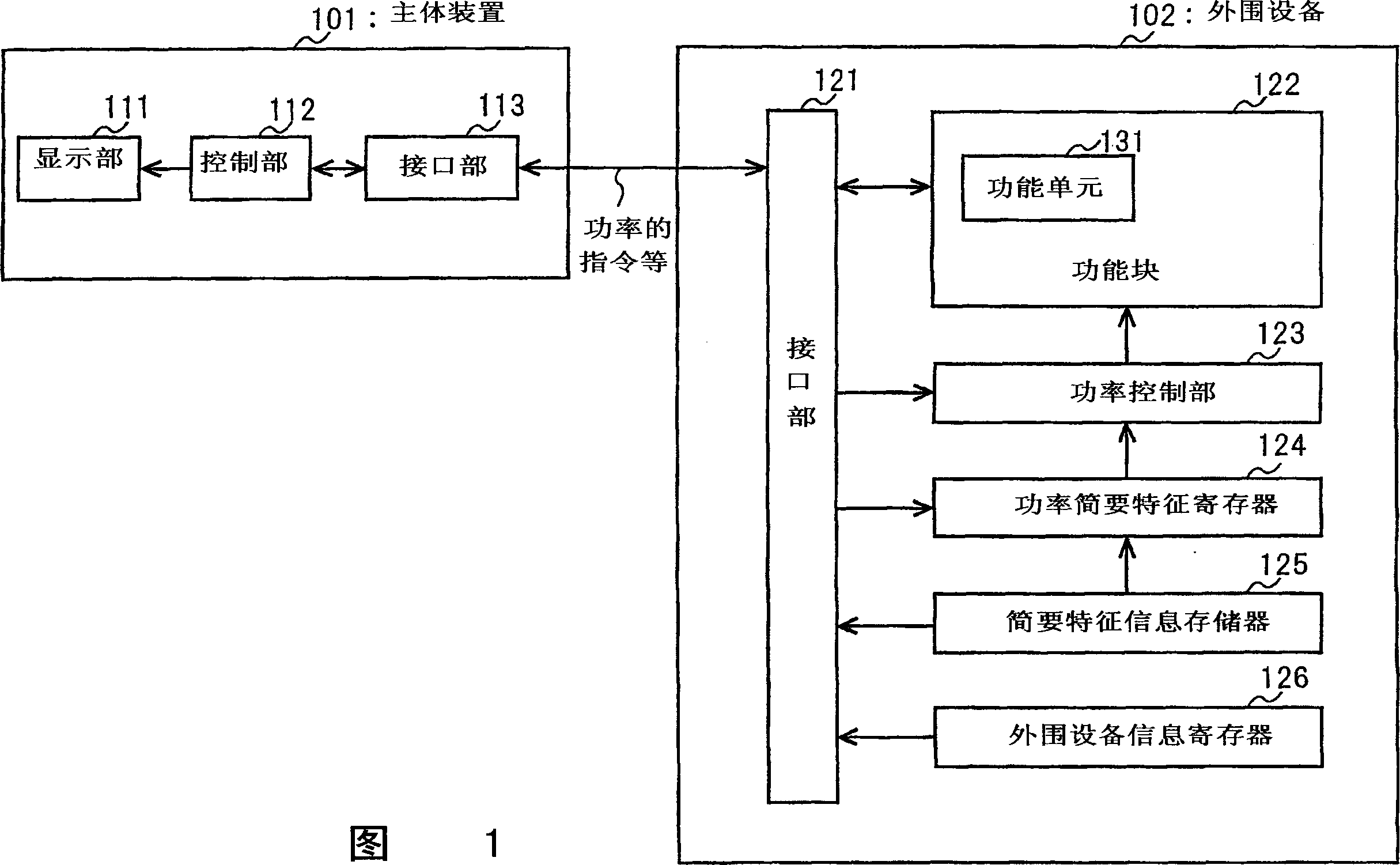
[0047] Use Figure 1~ Figure 4 , the peripheral device, its control method, its main device, its control method, and its program according to Embodiment 1 of the present invention will be described.
[0048] First, the configurations of the main device and peripheral devices of the first embodiment will be described. FIG. 1 is a block diagram showing the configurations of a main device and peripheral devices according to Embodiment 1 of the present invention. In FIG. 1 , 101 is a main device, and 102 is a peripheral device. The main body device 101 has a display unit 111 , a control unit 112 , and an interface unit 113 . The peripheral device 102 has an interface unit 121 , a function block 122 , a power control unit 123 , a power profile profile register 124 , a power profile profile information memory 125 , and a peripheral device information register 126 . The functional block 122 has a functional unit 131 .
[0049] In Embodiment 1, the main device 101 is a computer, a...
Embodiment 2
[0078] With Figure 5, Figure 6 , the peripheral device, its control method, its main device, its control method, and its program according to Embodiment 2 of the present invention will be described.
[0079] First, the configurations of the main device and peripheral devices of the second embodiment will be described. 5 is a block diagram showing configurations of a main device and peripheral devices according to Embodiment 2 of the present invention. The difference from Embodiment 1 (FIG. 1) is that a functional unit is added to the peripheral device. Except for this, the main device and peripheral devices of the second embodiment are the same as those of the first embodiment. In FIG. 5 (Example 2), the same components as those in FIG. 1 (Example 1) are assigned the same reference numerals, and description thereof will be omitted.
[0080] In FIG. 5 , 101 is a main device, and 502 is a peripheral device. The main body device 101 has a display unit 111 , a control unit 11...
Embodiment 3
[0095] With Figure 7, Figure 8 , the peripheral device, its control method, its main device, its control method, and its program according to Embodiment 3 of the present invention will be described.
[0096] First, the configurations of the main device and peripheral devices of the third embodiment will be described. Fig. 7 is a block diagram showing the configurations of a main device and peripheral devices according to Embodiment 3 of the present invention. The difference from Embodiment 2 (FIG. 5) is that a power profile determination unit is added to the peripheral device, instead of the main device, the power profile determination unit determines the power profile information set in the power profile register. Except for this, the main device and peripheral devices of the third embodiment are the same as those of the second embodiment. In FIG. 7 (Example 3), the same components as in FIG. 5 (Example 2) are assigned the same reference numerals, and description thereof w...
PUM
 Abstract
Description
Claims
Application Information
 - R&D
- Intellectual Property
- Life Sciences
- Materials
- Tech Scout
- Unparalleled Data Quality
- Higher Quality Content
- 60% Fewer Hallucinations
Browse by: Latest US Patents, China's latest patents, Technical Efficacy Thesaurus, Application Domain, Technology Topic, Popular Technical Reports.
© 2025 PatSnap. All rights reserved.Legal|Privacy policy|Modern Slavery Act Transparency Statement|Sitemap|About US| Contact US: help@patsnap.com


