
Method for detecting fault by near-end node

A node detection and remote node technology, applied in digital transmission systems, electrical components, transmission systems, etc., can solve problems such as manual configuration errors, service interruptions, and inability to implement non-MPLS return paths, so as to avoid errors and simplify configurations Effect

Inactive Publication Date: 2006-11-29
HUAWEI TECH CO LTD
View PDF0 Cites 7 Cited by
  • Summary
  • Abstract
  • Description
  • Claims
  • Application Information

AI Technical Summary

Problems solved by technology

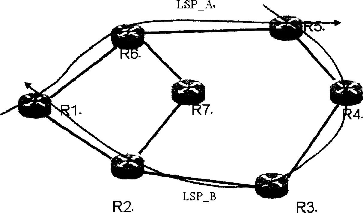
[0020] The TTSI, LSP incoming label, or reverse LSP configuration of the near-end node and the remote node are different, resulting in service failure;
[0021] The detection type or detection frequency configuration of the near-end node and the remote node are different, resulting in abnormal detection;
[0022] The reverse channel can only be an LSP, and a non-MPLS return path cannot be implemented, and when the reverse LSP is removed or cannot be forwarded, the BDI message cannot reach the remote node, and the remote node cannot know the defect;
[0023] At the same time, it is necessary to manually configure the near-end node and remote node of the LSP twice. When performing MPLS OAM detection of multiple LSPs, a lot of configuration work is required, and manual configuration errors will also be introduced;
[0024] When the detection of the near-end node and the remote node are not enabled at the same time, the detection is abnormal. For example, the detection of the near-end node is started before the remote node, or the detection of the remote node is stopped before the near-end node, and LOCVD is detected by mistake;
[0025] When it is necessary to modify the type and frequency of connectivity detection packets, the OAM function must be stopped on the remote node and the near-end node respectively, and the configuration of both ends must be re-modified before enabling the detection separately, which is inconvenient to use.

Method used


Image

  • Method for detecting fault by near-end node
  • Method for detecting fault by near-end node

Examples


Embodiment Construction

[0055] The core of the present invention is: in MPLS OAM detection, for the near-end node of LSP obtains the message information that remote node sends, by analyzing this message information; The operation of the near-end node.

[0056] Describe the present invention in detail below in conjunction with accompanying drawing:

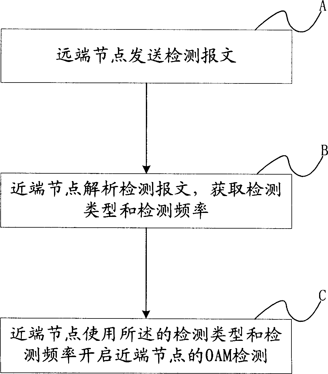
[0057] The specific processing flow of the method of the present invention is as follows figure 2 Shown:

[0058] In step A, the remote node of the LSP sends a detection message to the near-end node.

[0059] The detection message is the first message that the remote node reaches the near-end node through the LSP.

[0060] Step B, the near-end node of the label conversion path parses the detection message, and obtains the detection type and detection frequency of the detection message;

[0061] The detection types include: connectivity detection CV or fast defect detection FFD.

[0062] Step C, the near-end node uses the detection type and the detec...


PUM


Abstract

This invention relates to a method for testing faults by near-end nodes including: A, a remote node of a LSP sends a test report to a near end node, B, the near end node of said LSP analyzes said test report to get the test kind and frequency of the report, C, said near node uses said kind and frequency to start up operation management and maintains the OAM test.

Description

technical field [0001] The invention relates to the technical field of fault detection in computer communication, in particular to a method for detecting faults of near-end nodes. Background technique [0002] MPLS (Multiprotocol Label Switch, multi-protocol label switching) is a complex of switching and routing, which integrates network layer routing and link layer switching. And make the user network have greater flexibility in importing and implementing new network services. However, the control plane of the current MPLS technology network is still connectionless. In order to make the data plane of the traditional IP (Internet Protocol, Internet Protocol) network transition from "connectionless" to "connection", ATM (Asynchronous Transfer Mode) is introduced. , asynchronous transfer mode) fixed-length label switching ideas, to achieve carrier-class next-generation network. [0003] MPLS technology seamlessly integrates the flexibility of IP routing technology and the si...

Claims


Application Information

Patent Timeline
IPC IPC(8): H04L12/26
Inventor 刘光涛胡颖王玉婷
Owner HUAWEI TECH CO LTD
Learn More