
System for on-chip testing clock signal dither

A clock signal and system-on-chip technology, applied in the direction of electronic circuit testing, automatic power control, electrical components, etc., can solve the problems of long test time, linearity limitation of variable delay line, etc., and achieve the effect of unilateral delay

Inactive Publication Date: 2010-04-21
PEKING UNIV SHENZHEN GRADUATE SCHOOL
View PDF5 Cites 0 Cited by
  • Summary
  • Abstract
  • Description
  • Claims
  • Application Information

AI Technical Summary

Problems solved by technology

In order to solve the problem of the linearity limitation of the variable delay line, a delay line architecture that is not affected by component variability can be used, but the disadvantage is that it requires a long test time

Method used


Image

  • System for on-chip testing clock signal dither
  • System for on-chip testing clock signal dither
  • System for on-chip testing clock signal dither

Examples


Embodiment Construction

[0044] The present invention will be described in further detail below in conjunction with the accompanying drawings.

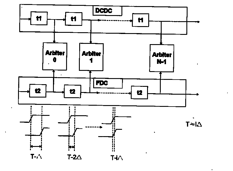
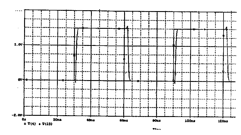
[0045] The present invention adopts the Vernier Delay line measurement method to measure the jitter of the clock signal, and the present invention realizes the Vernier Delay line measurement method by adopting an analog controllable unilateral delay line. The so-called unilateral delay refers to controlling the delay line so that the rising edge of the clock passing through the delay line is retreated, while the falling edge only moves a little.

[0046] Such as Figure 3A , 3B , 3C, and 3D are the delay results of the unilateral delay line of the present invention under different control conditions of Vcontrol. The line with hollow dots in the figure is the reference clock, while the line with solid dots is the delay result with different Vcontrol delays. Fig. 3 is the result of a schematic experiment about unilateral delay control, the experiment adopts ...


PUM


Abstract

The present invention relates to an on-chip system for testing clock signal flutter and its method, in particular, it relates to test of phase-locked loop flutter. The high time analyticity, low amplitude and differential signal are not influenced by element changeability. It includes subthreshold current control one-sided delay line with N time-delay units, reference delay line and test clock delay line. Besides, it also includes a arbiter and a calibrator. Said invention also provides the concrete steps of its test method.

Description

technical field [0001] The invention relates to an integrated circuit on-chip test system and test method, in particular to an on-chip system and method for testing clock signal jitter, especially to a phase-locked loop jitter test system and method. Background technique [0002] The current main development trend of integrated circuits is high speed, low power consumption, and small area. With the continuous improvement of the speed of digital circuits, the design of high-frequency clocks has become the main contradiction. In large-scale digital integrated circuits, even more than half of the The area is used for the clock tree circuit. In order to realize high-frequency clock frequency and other designs related to high-frequency applications, a phase-locked loop circuit (PLL) is required to realize the synchronization of the clock circuit in most occasions. The meaning of phase locking is the automatic control of phase synchronization. The automatic control closed-loop sy...

Claims


Application Information

Patent Timeline
Patent Type & Authority Patents(China)
IPC IPC(8): G01R31/28H03L7/08
Inventor 余菲
Owner PEKING UNIV SHENZHEN GRADUATE SCHOOL
Learn More