Electric double layer capacitor
A technology for electric double layer capacitors and batteries, which is applied in the directions of double layer capacitors, electrolytic capacitors, capacitors, etc., can solve the problems of insufficient expansion of the electric double layer area.
- Summary
- Abstract
- Description
- Claims
- Application Information
AI Technical Summary
Problems solved by technology
Method used
Image


Examples
Embodiment approach 1
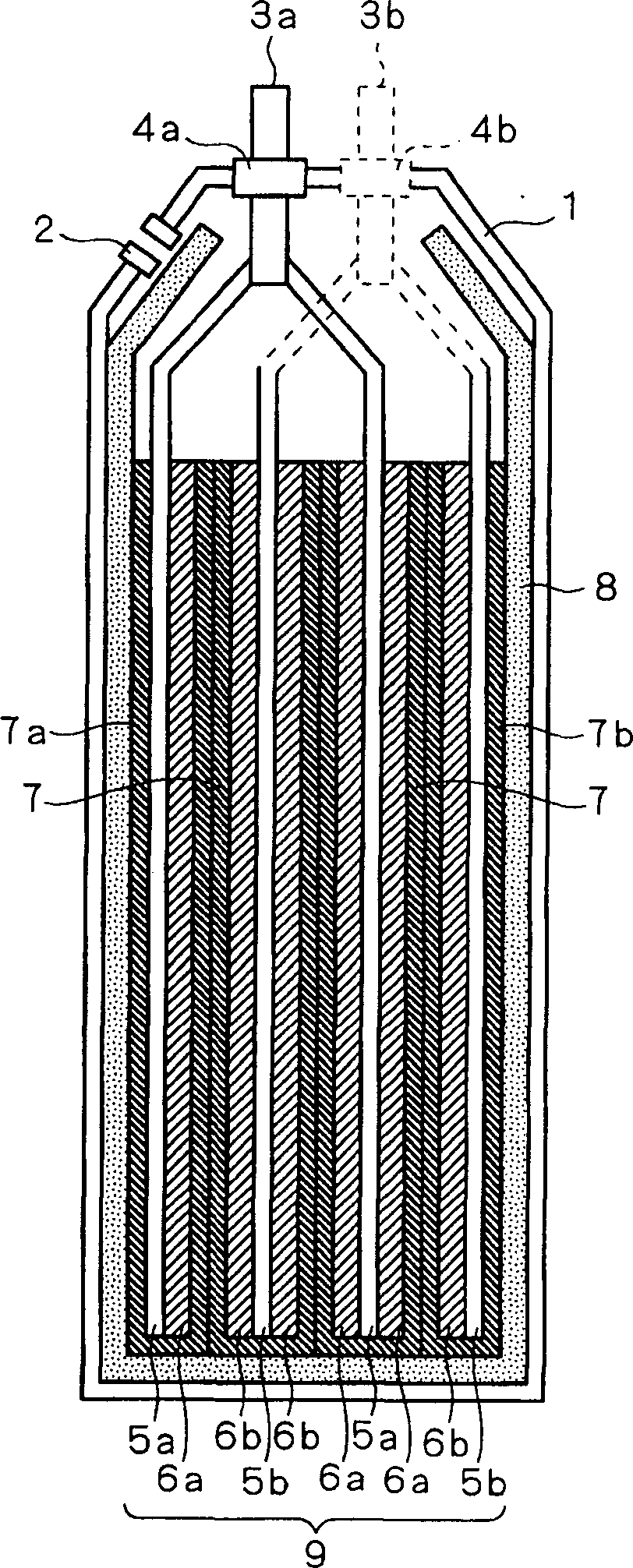
[0058] figure 1 and figure 2 These are a cross-sectional view and a front view showing the structure of the electric double layer capacitor according to Embodiment 1 of the present invention, respectively. refer to figure 1 , 2 It can be seen that the battery (cell) section 9 is constituted by laminating a plurality of positive electrodes 6 a and negative electrodes 6 b facing each other with the porous separator 7 interposed therebetween. As the positive electrode 6a and the negative electrode 6b, activated carbon with a diameter of about 10 μm and nano-gate carbon are bonded with a fluorine-based resin such as PTFE (polytetrafluoroethylene) as a binder, and a layer with a thickness of several hundred μm can be used. .
[0059] The positive electrode 6a is formed on the positive electrode current collector plate 5a, and the negative electrode 6b is formed on the negative electrode current collector plate 5b. Aluminum foil can be used as the positive electrode current co...
Embodiment approach 2
[0077] Figure 6 For a perspective view showing the structure of the electric double layer capacitor according to Embodiment 2 of the present invention, a part of the case 1 and the electrolytic solution reservoir 8 are shown cut away. in addition, Figure 7 Sectioned by virtual plane 20 for schematic illustration Figure 6 A cross-sectional view showing the cross-sectional structure of the electric double-layer capacitor shown.
[0078] In the first embodiment described above, an example of a multilayer type electric double layer capacitor was described, such as Figure 6 , 7 As shown, the present invention is also applicable to wound type electric double layer capacitors.
[0079] The electric double layer capacitor of the winding type differs from the laminated type in that each sheet of the positive electrode 6a, the separator 7, and the negative electrode 6b is stacked and wound multiple times to form the battery part 9. The structure of the electric double layer cap...
Embodiment approach 3
[0082] Figure 8 It is a front view showing the structure of an electric double layer capacitor according to Embodiment 3 of the present invention. Such as Figure 8 As shown, the electric double layer capacitor according to Embodiment 3 has a case 101 , an electrolytic solution reservoir 104 and a battery unit 105 accommodated in the case 101 , and a positive terminal 102 and a negative terminal 103 . The electrolytic solution reservoir 104 is constituted by a plurality of electrolytic solution reservoirs 104a.
[0083] Figure 9 and Figure 10 These are a cross-sectional view and a perspective view showing the structures of the electrolytic solution reservoir 104 and the battery unit 105 in a state housed in the casing 101 , respectively. exist Figure 10 , for convenience of illustration, not shown in Figure 9 Separator 110 shown in . Such as Figure 9 , 10 As shown, the battery unit 105 has a structure in which a plurality of sets of positive electrodes 106 and n...
PUM
| Property | Measurement | Unit |
|---|---|---|
| Diameter | aaaaa | aaaaa |
| Thickness | aaaaa | aaaaa |
| Thickness | aaaaa | aaaaa |
Abstract
Description
Claims
Application Information
 - Generate Ideas
- Intellectual Property
- Life Sciences
- Materials
- Tech Scout
- Unparalleled Data Quality
- Higher Quality Content
- 60% Fewer Hallucinations
Browse by: Latest US Patents, China's latest patents, Technical Efficacy Thesaurus, Application Domain, Technology Topic, Popular Technical Reports.
© 2025 PatSnap. All rights reserved.Legal|Privacy policy|Modern Slavery Act Transparency Statement|Sitemap|About US| Contact US: help@patsnap.com