


Quick Research
Generate reliable direction feasibility study reports for your R&D in just a few steps.

Technical Q&A
Discover and master advanced knowledge NOW. Basics, ideas, possibilities, all at once.

Find Solutions
As an expert in R&D theories, this can generate solutions to your technical problems instantly.

Evaluate Feasibility
Analyze your overall solution with one click, know your potential R&D risks in advance.

Monitor Landscape
Get weekly tech updates, stay abreast of the latest tech innovations and key insights.
Rapid-clamp driver
A drive, fast technology, applied in the direction of workpiece clamping device, sorting, manufacturing tools, etc., can solve the problems of long time, unsatisfactory sorting machine, complex structure, etc., to achieve convenient operation, shorten auxiliary time, and simple structure Effect
- Summary
- Abstract
- Description
- Claims
- Application Information
AI Technical Summary
Problems solved by technology
Method used
Image

Examples
Embodiment Construction
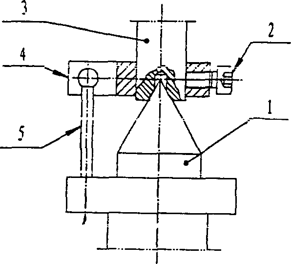
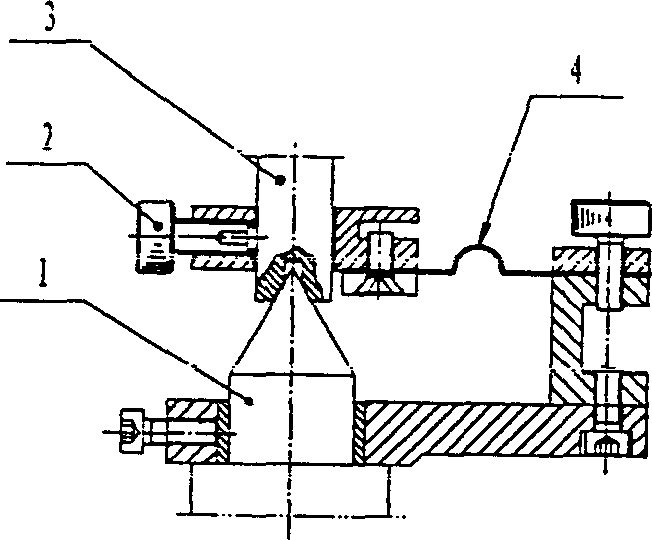
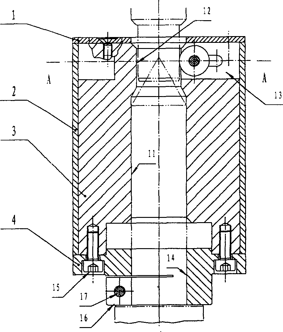
[0018] The present invention is made up of parts 1-8, and the fixed seat 4 and the driver seat 3 are fastened together by M4 screws. And fasten part 4 coaxially with the main shaft of the sorting machine with M4 screws. The clamping mechanism composed of bearing 5 (sliding bearing or deep groove ball bearing, pin shaft 6, and washer 7) is installed on the driver seat; the elastic stopper 8 is used to make the bearing 5 tightly pressed against the shaft of the gear shaft under test On the neck. When the journal of the shaft gear is put into the inner hole of the driver, the top center quickly pushes the top hole of the journal of the shaft gear into the top of the main shaft of the instrument. When the main shaft rotates, the driver rotates synchronously with it. Since the bearing 5 is tight The ground is pressed on the journal of the measured shaft gear, so that the shaft gear also rotates synchronously with the main shaft. The inner hole of the drive seat 3 has chamfers, whic...
PUM
 Abstract
Description
Claims
Application Information
 - R&D Engineer
- R&D Manager
- IP Professional
- Industry Leading Data Capabilities
- Powerful AI technology
- Patent DNA Extraction
Browse by: Latest US Patents, China's latest patents, Technical Efficacy Thesaurus, Application Domain, Technology Topic, Popular Technical Reports.
© 2024 PatSnap. All rights reserved.Legal|Privacy policy|Modern Slavery Act Transparency Statement|Sitemap|About US| Contact US: help@patsnap.com