
Outer shuttle of sewing machine and its making process

A manufacturing method and sewing machine technology, which are applied to sewing machine components, ferrule mechanisms for sewing machines, sewing equipment, etc., can solve the problems of low strength and toughness, low production efficiency, and difficult manufacturing.

Inactive Publication Date: 2006-10-18
YUAN FONG PRECISION TECH
View PDF0 Cites 5 Cited by
  • Summary
  • Abstract
  • Description
  • Claims
  • Application Information

AI Technical Summary

Problems solved by technology

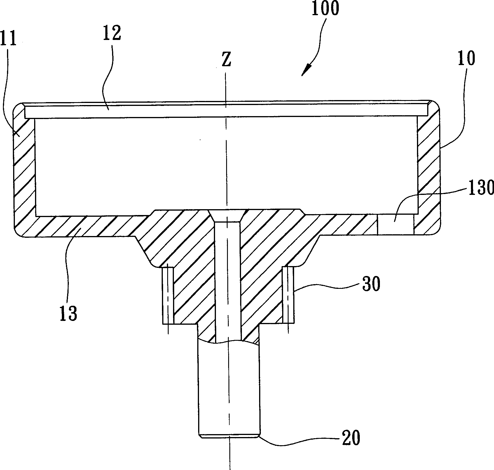
[0005] However, because the shuttle body 10, the engaging element 30 and the rotating shaft 20 of the outer shuttle 100 are stepwise and integrally made of metal material, and the engaging element 30 is adjacent to the shuttle body 10, it is comparatively difficult to manufacture. Difficult, it needs to go through multi-channel turning, milling, grinding, polishing... and other operations. Heavy, for the outer shuttle that needs to rotate at high speed, it also increases the loss of transmission power
[0006] Based on this, in order to improve the above-mentioned deficiencies, some operators use plastic injection molding to integrally inject and mold the entire outer shuttle 100. Although the outer shuttle made can greatly reduce the weight and simplify the previous manufacturing process, the plastic material The outer shuttle 100 made also has quite serious shortcomings in subsequent processing and manufacturing. The main reason is that the hook point 111 of the shuttle body 10 must be quite sharp and smooth, so the outer shuttle embryo after injection molding often still needs to be re-injected. After a processing step of cutting out the hook point 111, since the strength and toughness of the plastic material are lower than those of metal, in the process of cutting, if there is a little carelessness, it is easy to cause the breakage of the hook point 111 , breakage, resulting in an increase in the rate of defective products, and even if the hook tip 111 is not broken, there may still be a stress concentration phenomenon that is difficult to identify with the naked eye. As a result, the service life of the outer shuttle is reduced. The outer shuttle molded by injection molding of plastic materials still has its blind spots that are difficult to overcome in processing and manufacturing, so it is not a good manufacturing method

Method used


Image

  • Outer shuttle of sewing machine and its making process
  • Outer shuttle of sewing machine and its making process
  • Outer shuttle of sewing machine and its making process

Examples


Embodiment Construction

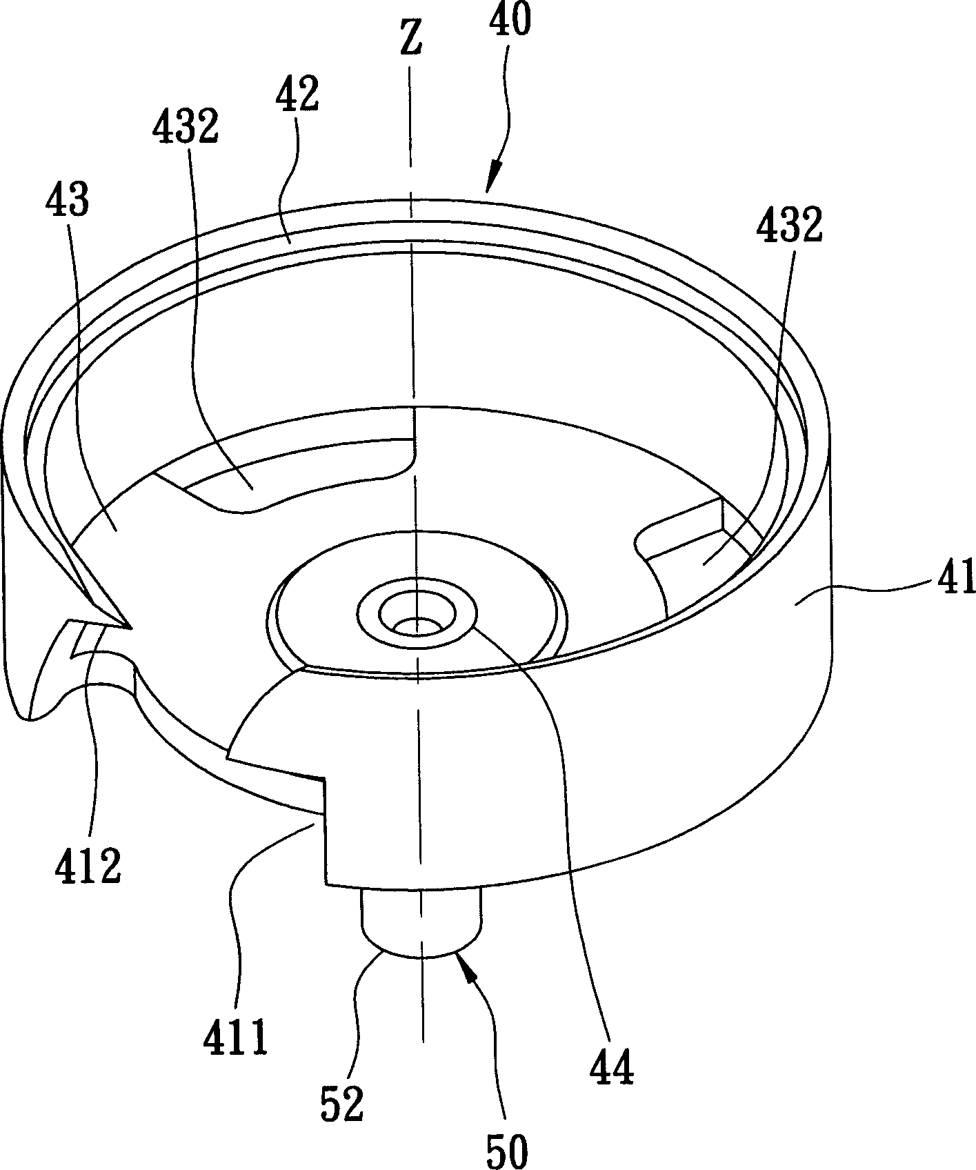
[0027] Such as image 3 , 4 As shown, a preferred embodiment of the outer shuttle of the sewing machine of the present invention is suitable for being sleeved on the outside of the inner shuttle of a sewing machine (not shown), and the outer shuttle of the sewing machine includes a shuttle body 40, a rotating shaft 50, and an engaging Element 60.

[0028] The shuttle body 40 is made of metal material and surrounds an axis Z to accommodate the inner shuttle. The shuttle body 40 includes a peripheral wall 41 surrounding the axis Z, an opening 42 formed at one end of the peripheral wall 41, a The bottom wall 43 at the other end of the peripheral wall 41, and a perforation 44 pierced through the bottom wall 43 along the axis Z direction. One side of the peripheral wall 41 has a needle groove 411, and a needle groove 411 from the peripheral wall 41 toward the The hook point 412 extending from the needle track groove 411, and the side of the bottom wall 43 adjacent to the needle t...


PUM


Abstract

The present invention is outer shuttle of sewing machine and its making process. The outer shuttle includes one shuttle body, one rotating shaft and one mesh element. The shuttle body made of metal material includes one side wall around some axis, one notch in one end of the side wall, one bottom wall on the other end of the side wall, and one axial hole in the bottom wall. The rotating shaft includes one first end in the hole, one opposite second end far from the hole and one material jetting hole extending from the first end to the outer ring face. The mesh element around the rotating shaft is formed with plastic and through jetting molding and has one locating part stretched into the material jetting hole. The outer shuttle of the present invention has high strength and light weight.

Description

【Technical field】 [0001] The invention relates to a horizontal outer shuttle for a sewing machine, in particular to an outer shuttle of a sewing machine and a manufacturing method thereof. 【Background technique】 [0002] Such as figure 1 , 2 As shown, the outer shuttle 100 of the conventional sewing machine is used to be sleeved on the outside of the inner shuttle of a sewing machine. The outer shuttle 100 is made of metal material, and mainly includes a shuttle body 10 and an engaging element 30 with decreasing outer diameters. (chainring) and a rotating shaft 20 three main structures, wherein. [0003] The shuttle body 10 is used to accommodate the inner shuttle, and includes a peripheral wall 11 around an axis Z, an opening 12 formed at one end of the peripheral wall 11, and a bottom wall 13 formed at the other end of the peripheral wall 11. One side of 11 has a needle track groove 110, and a hook tip 111 extending from the peripheral wall 11 toward the needle track gr...

Claims


Application Information

Patent Timeline
IPC IPC(8): D05B57/26B29C45/14
Inventor 李崇仁
Owner YUAN FONG PRECISION TECH
Learn More