
Heat interface material and its making process

A technology of thermal interface materials and manufacturing methods, applied in heat exchange materials, chemical instruments and methods, semiconductor/solid-state device manufacturing, etc., can solve the problems of carbon nanotube interface thermal resistance reduction, large additional pressure, and insufficient contribution

Active Publication Date: 2006-10-18
TSINGHUA UNIV +1
View PDF1 Cites 30 Cited by
  • Summary
  • Abstract
  • Description
  • Claims
  • Application Information

AI Technical Summary

Problems solved by technology

However, the contribution of carbon nanotubes in this thermal interface material to the reduction of interface thermal resistance is insufficient, and a large additional pressure is still required for packaging

Method used


Image

  • Heat interface material and its making process
  • Heat interface material and its making process
  • Heat interface material and its making process

Examples


Embodiment Construction

[0032] The present invention will be described in further detail below in conjunction with the accompanying drawings.

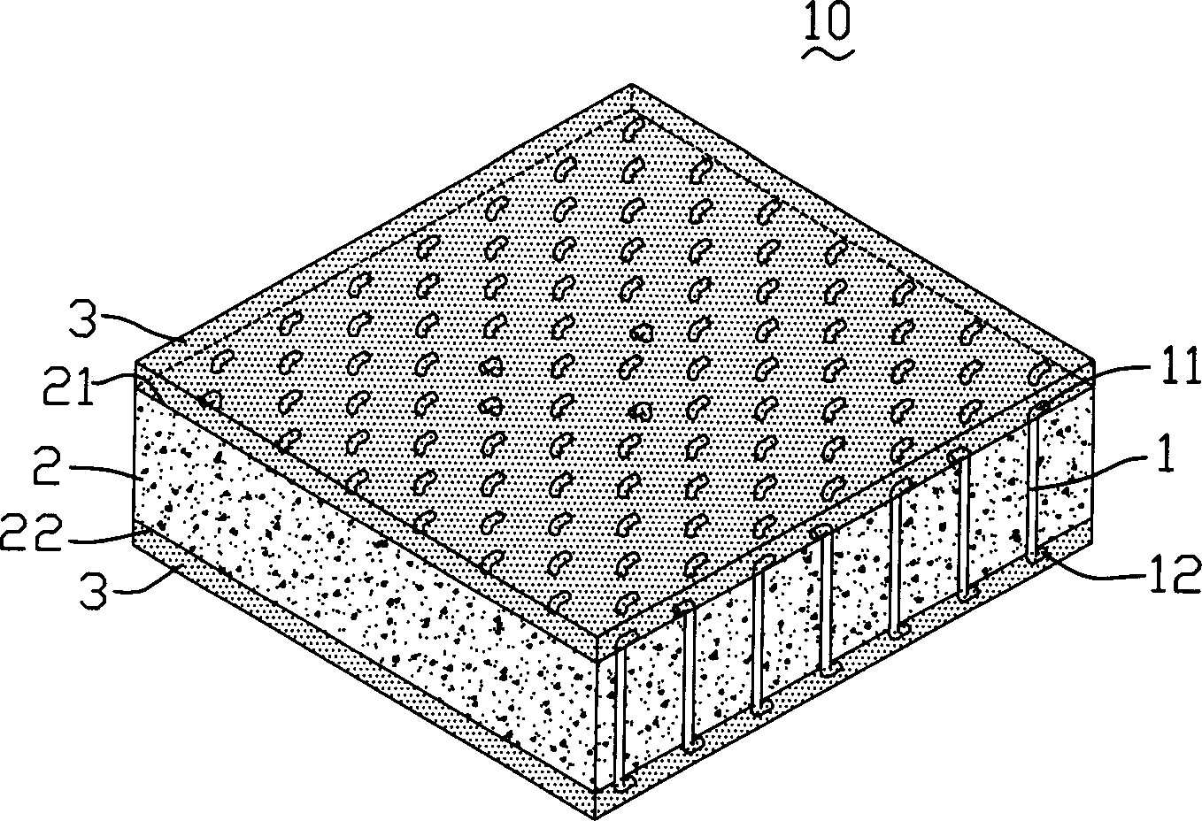
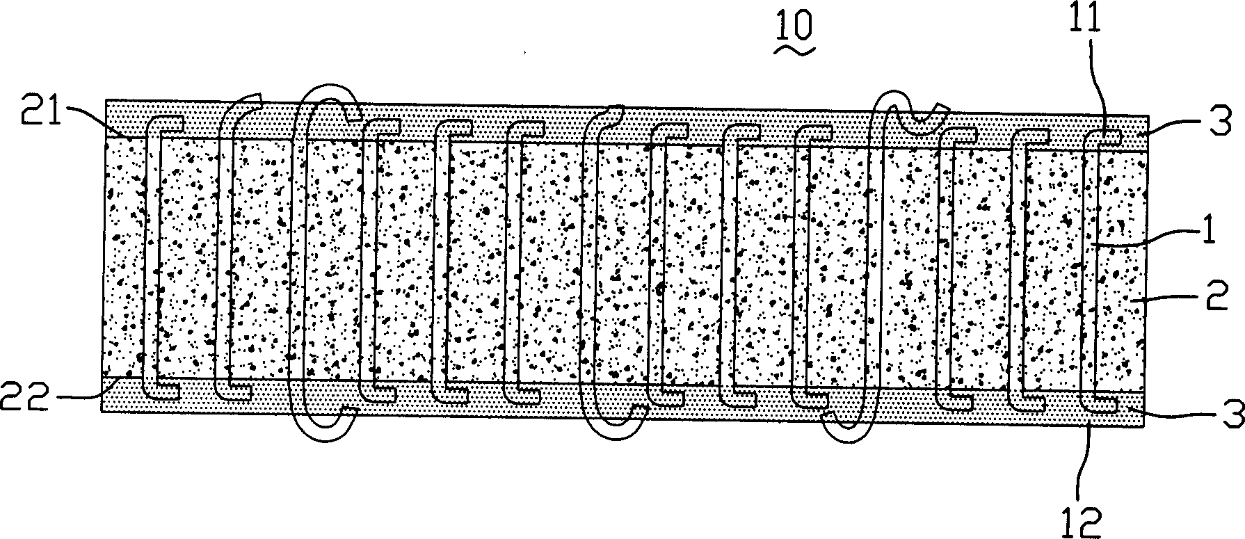
[0033] see figure 1 and figure 2 , are respectively a perspective view and a side view of the thermal interface material in the embodiment of the technical solution. The thermal interface material 10 includes a matrix 2 , a plurality of carbon nanotubes 1 dispersed in the matrix 2 , and a phase change material layer 3 formed on at least one surface of the matrix 2 . The base body 2 has a first surface 21 and a second surface 22 opposite thereto. The surface area of ​​the first surface 21 may be equal to or not equal to the surface area of ​​the second surface 22 .

[0034] The base 2 can be selected from a polymer material, such as silicone rubber, polyester, polyvinyl chloride, polyvinyl alcohol, polyethylene, polypropylene, epoxy resin, polycarbonate, polyoxymethylene, polyacetal, etc. The material, such as Sylgard 160, is Sylgard 160 type A, B two-comp...


PUM

PropertyMeasurementUnit
phase transition temperatureaaaaaaaaaa

Abstract

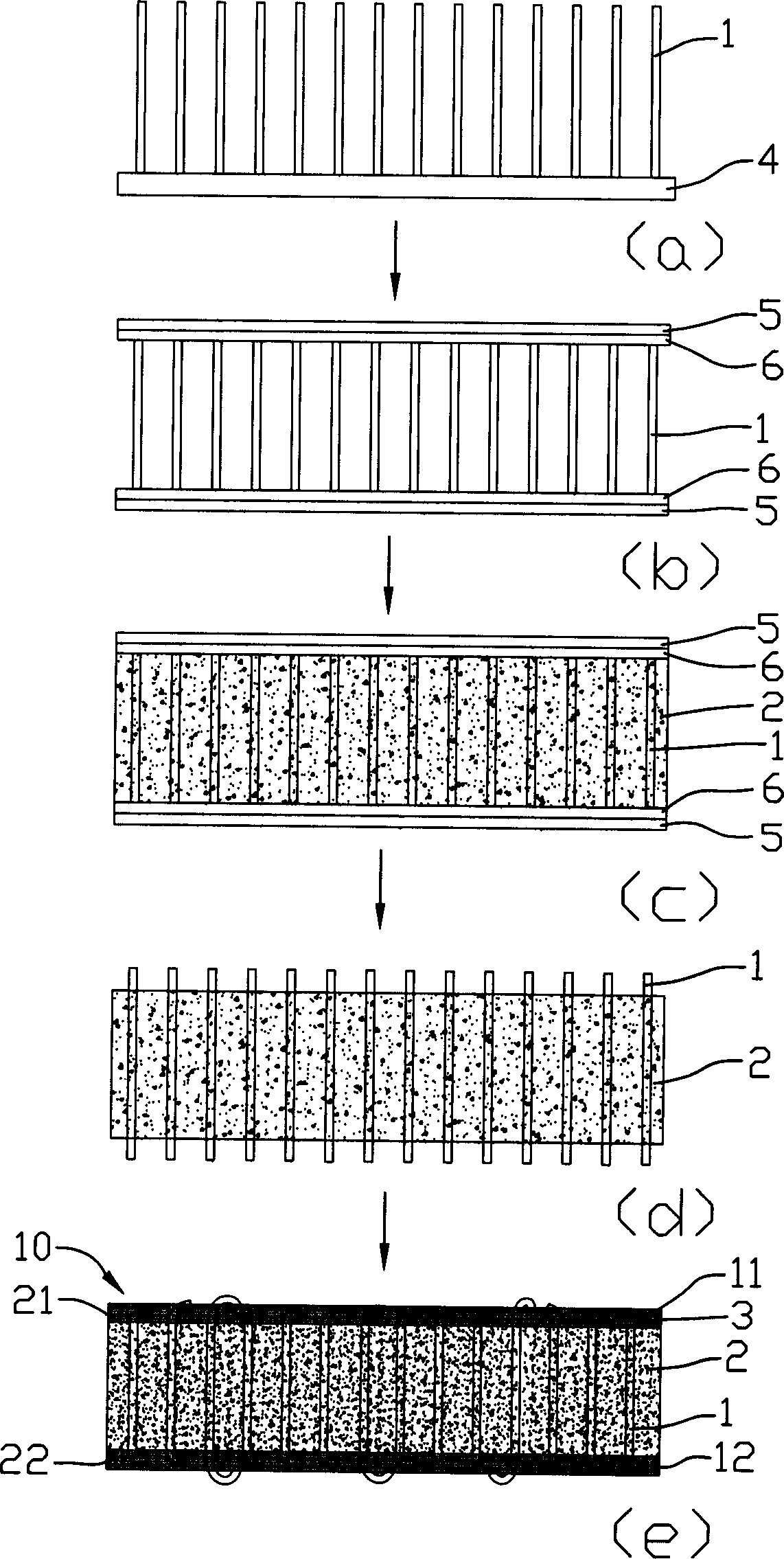
The heat interface material includes one base body and carbon nanotubes distributed inside the base body. The base body includes one first surface and one opposite second surface, and the carbon nanotubes extend from the first surface to the second surface and extend beyond at least one surface to bend elastically inside a phase change material layer formed in the surface. The present invention also provides the making process of the heat interface material. Owing to the carbon nanotubes with at least one end elastically bending in the phase change material, the heat interface material has good heat interface contact, low heat resistance and high heat conducting efficiency.

Description

【Technical field】 [0001] The invention relates to a thermal interface material, in particular to a thermal interface material with carbon nanotube material and a manufacturing method thereof. 【Background technique】 [0002] As integrated circuits become denser and miniaturized, electronic components become smaller and operate at higher speeds, placing ever higher demands on heat dissipation. Therefore, in order to dissipate the heat from the heat source as soon as possible, it has become a common practice in the industry to install a heat sink on the surface of the electronic component. It uses the high thermal conductivity of the material of the heat sink to quickly dissipate the heat to the outside. However, the surface of the heat sink and the heat source There is often a certain gap in the contact, so that the heat sink and the surface of the heat source are not in close contact, which has become a major defect in the heat dissipation of the heat sink. Aiming at the con...

Claims


Application Information

Patent Timeline
Patent Type & Authority Applications(China)
IPC IPC(8): B32B5/00C09K5/02H01L21/34
CPCH01L23/373Y10S977/742H01L2924/0002Y10T428/30H01L2924/00
Inventor 黄华刘长洪范守善
Owner TSINGHUA UNIV
Learn More