
Power controller

A technology of power controller and controller, which is applied to control/regulating systems, instruments, regulating electrical variables, etc., can solve the problems of complex manufacturing process and achieve the effect of low production cost

Inactive Publication Date: 2006-10-11
NXP BV
View PDF5 Cites 8 Cited by
  • Summary
  • Abstract
  • Description
  • Claims
  • Application Information

AI Technical Summary

Problems solved by technology

Therefore, the electrical equipment manufacturing supply market with different power grids has to manufacture various versions of products to suit different power sources, which complicates the manufacturing process

Method used


Image

  • Power controller
  • Power controller

Examples


Embodiment Construction

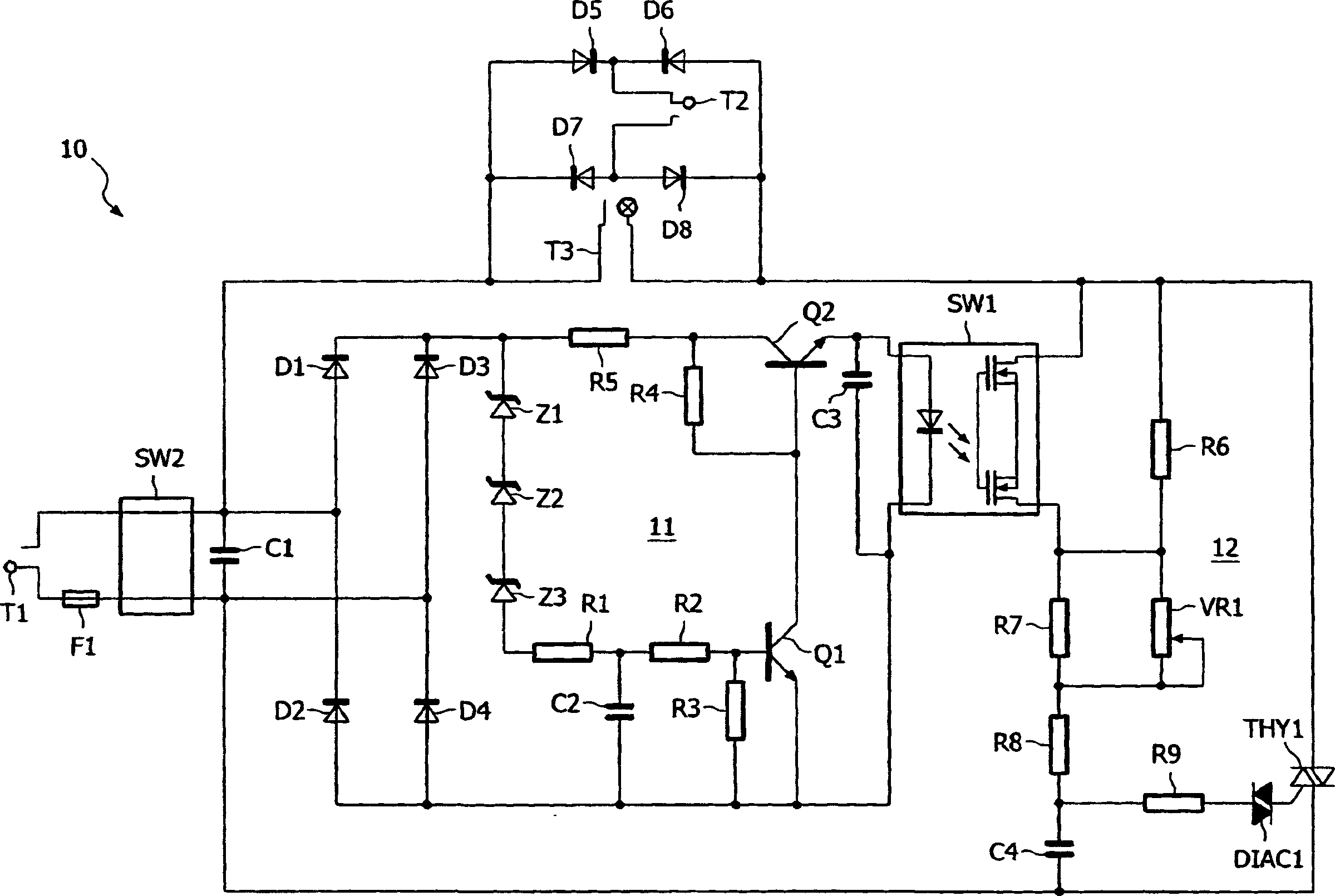
[0017] figure 1 The variable power controller includes an input terminal T1, which is connected to the main circuit through a fuse F1. exist figure 1 , the live terminal of input T1 is shown as the lowest and the highest terminal is the neutral terminal. A power switch SW2 is interposed between the terminals and the power controller circuit, and it is this power switch that is used to operate the circuit.

[0018] Generally, the power controller is configured to provide 110V, 50Hz or 60Hz power to the load connected to the output terminal T3. The power received by the input terminal T1 can be 110V or 240V, 50Hz or 60Hz.

[0019] The power controller 10 can be considered to be reconstituted by two main parts, a controller 11 and a trigger circuit 12, each of which is connected to receive power supplied to the input terminal T1. The first capacitor C1 is connected between output terminals of the power switch SW2. The first capacitor C1 is an X2-level capacitor, which can pr...


PUM


Abstract

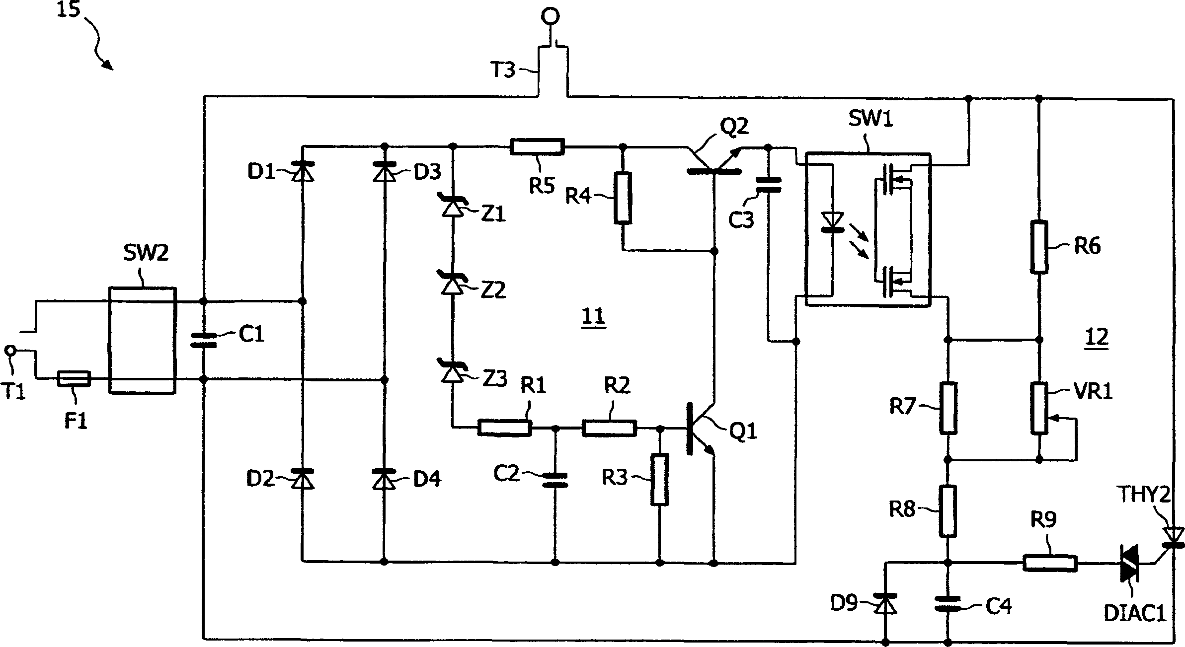
A power controller (10) includes a controller (11) and a trigger circuit (12). When the supply voltage received at terminal T1 exceeds a threshold, for example 120V RMS, the reversely connected zener diodes Z1 to Z3 conduct, turning on transistor Q1. This turns transistor Q2 off and normally open relay SW1 remains open. The switching or firing phase angle of triac THY1 is thus determined by the speed at which capacitor C4 is charged to a firing voltage by current flowing through resistors R6, R7, R8 and VR1. In this case, the trigger phase angle is when VR1 is at its maximum power setting (0 ohms), and 240V AC input power provides an effective 110V AC output at terminal T3. When the received supply voltage is less than the threshold, the transistor Q1 is turned off and the relay SW1 is activated. This resistor R6 is bypassed and causes the switch or trigger phase angle to adopt a value of about 0 degrees when VR1 is at the maximum power setting, so that the voltage at the output power terminal T3 is substantially the same as that received at terminal T1. same voltage.

Description

technical field [0001] The invention relates to a power controller for connecting loads to power supplies of different rated voltages. Background technique [0002] The power grid supply voltage is different in different parts of the world. For example, the AC power grid supply voltage in the United Kingdom is 230-240V, while the power grid supply voltage in other countries is 110-120V. Therefore, the electrical equipment manufacturing supply market with different power grids has to manufacture various versions of products to adapt to different power sources, which complicates the manufacturing process. [0003] US-A-5886422 and US-A-4654538 disclose power supplies providing a 220V full sine wave output for a 110V or 220V AC input. US-A-5162984 discloses a power supply with AC linear harmonic current correction. GB-A-2098368 provides a current limited fixed DC output corresponding to the input AC voltage range. US-A-4103388 provides a wide range of output AC voltages and...

Claims


Application Information

Patent Timeline
IPC IPC(8): G05F1/56
Inventor N·J·哈姆
Owner NXP BV
Learn More