Eureka AIR delivers breakthrough ideas for toughest innovation challenges, trusted by R&D personnel around the world.

Supersonic speed flow field detection system based on H-S wave front sensor and detection method thereof

A wavefront sensor and supersonic flow technology, applied in the flow field detection system and its detection field, can solve the problems of difficult to obtain quantitative data, high requirements, long time consumption, etc. Easy-to-use effects

Inactive Publication Date: 2006-10-11
INST OF OPTICS & ELECTRONICS - CHINESE ACAD OF SCI
View PDF0 Cites 34 Cited by
  • Summary
  • Abstract
  • Description
  • Claims
  • Application Information

AI Technical Summary

Problems solved by technology

This method can obtain some qualitative characteristics of the flow field, but the disadvantage is that it is difficult to obtain quantitative data
The principle of interferometry is to use the beam to be measured to interfere with the standard reference beam, and then process the interference fringes to obtain wavefront aberration data. The advantage is that quantitative data can be obtained, but the disadvantage is that the optical path of the interferometer needs to be adjusted to generate interference fringes. , takes a long time; and the interferometry has high requirements on the external environment, generally, to obtain a high-precision measurement, it needs to be operated on an air-cushion anti-vibration platform
The supersonic wind tunnel flow field is an environment with severe vibration and strong interference, which limits the application of interferometry.

Method used


Image

  • Supersonic speed flow field detection system based on H-S wave front sensor and detection method thereof
  • Supersonic speed flow field detection system based on H-S wave front sensor and detection method thereof
  • Supersonic speed flow field detection system based on H-S wave front sensor and detection method thereof

Examples


Embodiment Construction

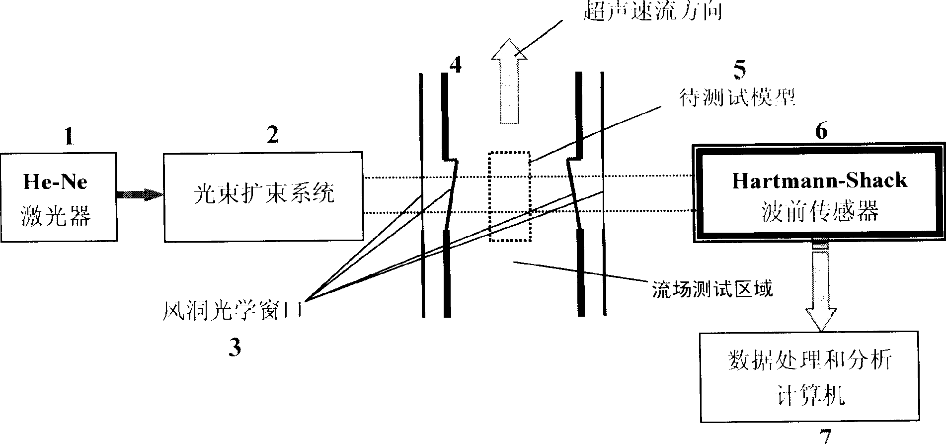
[0034] Such as figure 1As shown, the supersonic flow field detection system based on H-S wavefront sensor of the present invention consists of He-Ne laser light source 1, beam expander system 2, supersonic wind tunnel 4, model to be tested 5, H-S wavefront sensor 6, data processing Composed of an analysis computer 7, the model to be tested 5 has a transparent glass window made of K9, the He-Ne light source 1 is in front of the beam expander system 2, and the beam expander system 2 is located on the left side of the supersonic wind tunnel 4. In front of the window 3, the distance is about 0.5m. The supersonic wind tunnel 4 is located between the beam expander system 2 and the H-S wavefront sensor 6. The distance between the H-S wavefront sensor 6 and the optical window 3' on the right side of the supersonic wind tunnel 4 is about The data collected by the H-S wavefront sensor 6 is processed and analyzed by the computer 7, and the wavefront phase is restored by using the mode me...


PUM


Abstract

The invention discloses a supersonic speed flow field detecting system based on H-S wave front sensor, which is formed by a He-Ne laser, a light beam expander, a supersonic speed wind tunnel generating the flow field, a detected model, an H-S wave front sensor, a picture collecting card and a data collect processing computer. Wherein, the invention can easily attain the wave phase distribution of laser that has passed the flow field and the light beam aberration character, as wave three-dimensional distribution, PV valve, RMS, and Zernike aberration parameters, to attain the light beam remote field distribution, light beam mass center excursion character, encircled energy, etc, while said invention is based on Hageman-shark wave front sensor to effectively display the building, stabilizing and completing of said flow field. And the inventive data analyze processing software has better real-time property to apply flow field dynamic character detection.

Description

technical field [0001] The invention relates to a flow field detection system and a detection method thereof, in particular to a supersonic flow field detection system and a detection method based on a Hartmann-Shack (Hartmann-Shack) wavefront sensor. Background technique [0002] When performing optical detection or ranging on a supersonic vehicle, a complex external flow field will be formed on the periphery of the vehicle, including separation, turbulent boundary layer and wake development, seepage boundary layer and viscous wake interaction, etc., and may A complex vortex system and compression waves and expansion waves with different intensities are formed, including shock waves, etc., thereby forming a region with a strong gradient of density change, and these conditions vary with different states of the aircraft's flight. Such a complex flow field will cause various wavefront distortions during the laser transmission process. If the beam is transmitted over a long dis...

Claims


Application Information

Patent Timeline
Patent Type & Authority Applications(China)
IPC IPC(8): G01M10/00
Inventor 张翔王春鸿鲜浩
Owner INST OF OPTICS & ELECTRONICS - CHINESE ACAD OF SCI
Why Eureka
Eureka Blog
Learn More