Energy recovery and control circuit for electric vehicle and automobile chassis made thereof
A control circuit and energy recovery technology, applied in electric vehicles, vehicle energy storage, electric braking systems, etc., can solve the problems of battery overload, shortened battery life, and insufficient power of electric vehicles
- Summary
- Abstract
- Description
- Claims
- Application Information
AI Technical Summary
Problems solved by technology
Method used
Image
Examples
Embodiment Construction
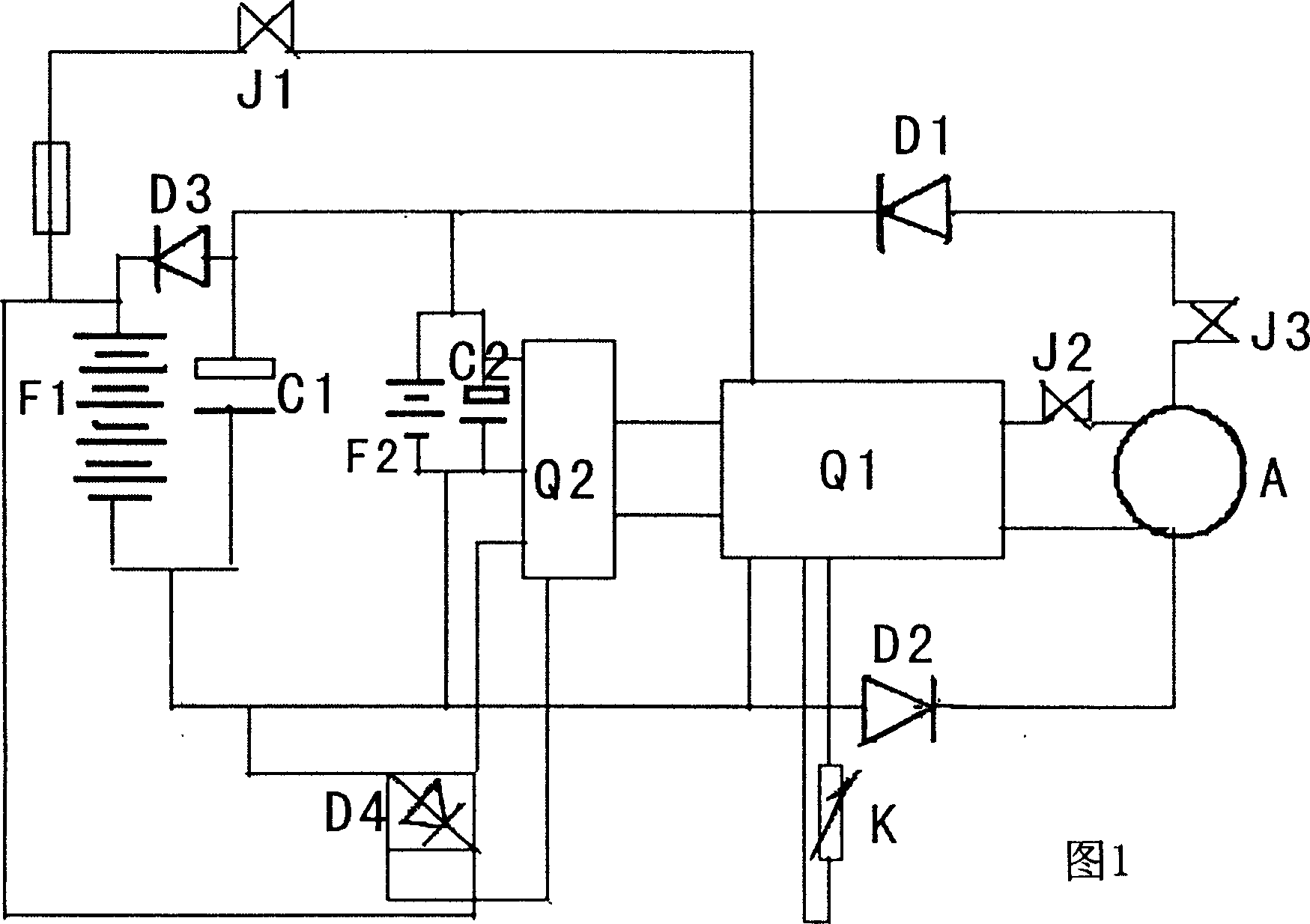
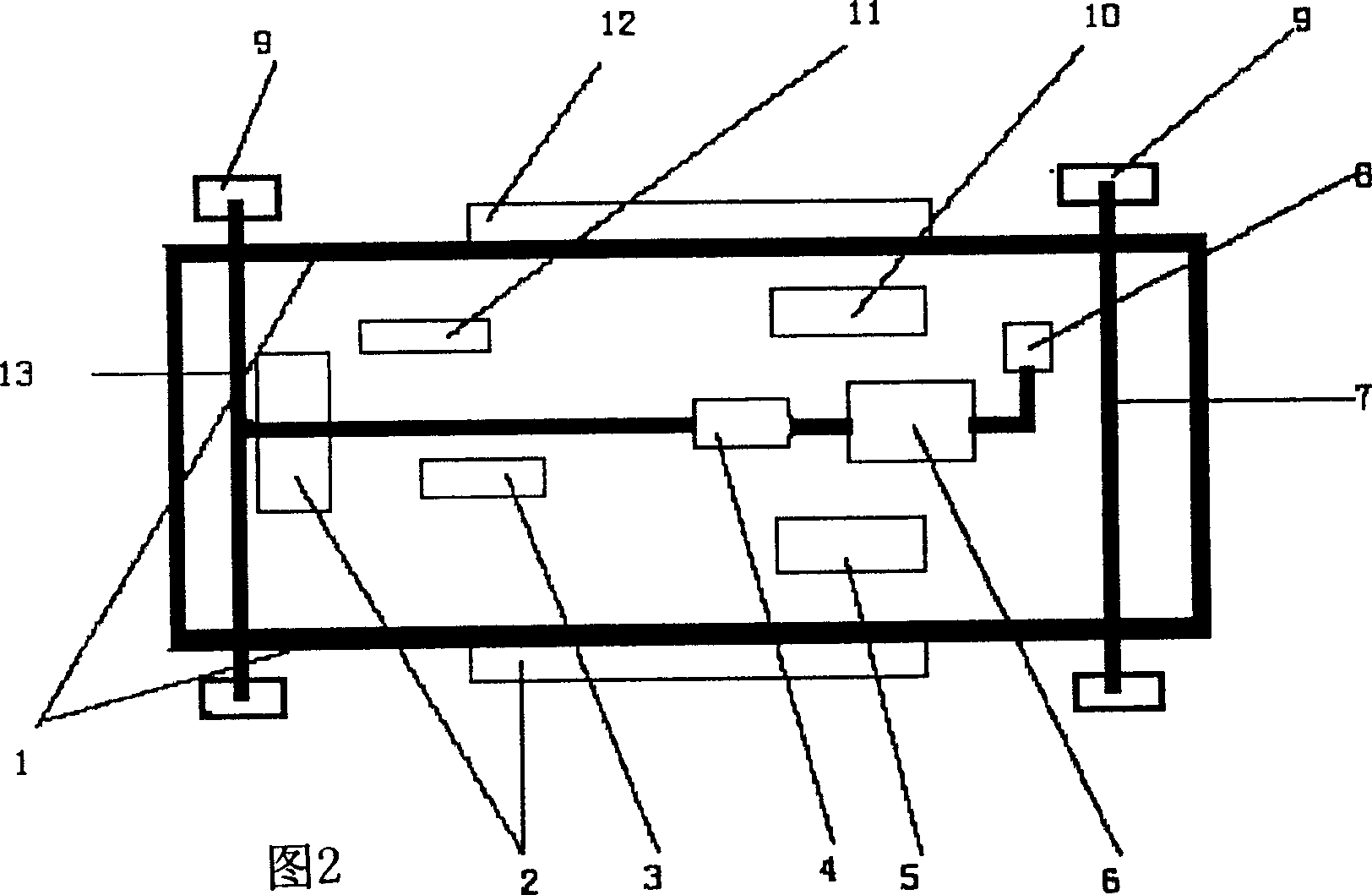
[0012] The electric vehicle energy recovery control circuit diagram is shown in Figure 1. Control circuit Q1 composed of microcomputer and DMOC645 electric speed controller (American Sun Electric Company), permanent magnet reluctance motor A, contactors J2 and J1 connected in series in the motor circuit, contactors connected in series in the generator circuit J3, diodes D1, D2 are the same as the corresponding parts in the existing electric vehicle energy recovery control circuit. The control circuit Q1 is mainly responsible for program control of functions such as speed regulation, braking, and energy recovery. A permanent magnet reluctance motor can be used as both a motor and a generator. The difference is the use of high and low voltage charging branches. Among them, the high-voltage charging branch is composed of a battery pack F1, a DC diode D3 and a large-capacity supercapacitor C1, and the battery pack F1 is connected in reverse series with the diode D3 and then conn...
PUM
 Abstract
Description
Claims
Application Information
 - R&D Engineer
- R&D Manager
- IP Professional
- Industry Leading Data Capabilities
- Powerful AI technology
- Patent DNA Extraction
Browse by: Latest US Patents, China's latest patents, Technical Efficacy Thesaurus, Application Domain, Technology Topic, Popular Technical Reports.
© 2024 PatSnap. All rights reserved.Legal|Privacy policy|Modern Slavery Act Transparency Statement|Sitemap|About US| Contact US: help@patsnap.com


