Hoist for elevator

A traction machine and elevator technology, which is applied to elevators, hoisting devices, transportation and packaging in buildings, etc., can solve problems such as troublesome sheave maintenance and inspection operations, and achieve the effect of easy maintenance and inspection operations.

Inactive Publication Date: 2006-08-23
MITSUBISHI ELECTRIC CORP
View PDF1 Cites 2 Cited by
  • Summary
  • Abstract
  • Description
  • Claims
  • Application Information

AI Technical Summary

Problems solved by technology

[0004] However, in the case of such a traction machine for an elevator, when both the sheave and the braking device are to be maintained and inspected separately, maintenance and inspection must be performed from both sides. Between the wall of the car and the lifting car, for example, in the wall area opposite to the sheave, a space for maintenance and inspection protruding to the opposite side of the car must be provided.
[0005] In addition, if there is no such space, the wear amount of the groove of the sheave and the gap between the rope latch and the rope cannot be directly confirmed visually. After confirming the amount of wear mentioned above, and then using a dedicated feeler gauge to confirm the above gap, there is a troublesome sheave inspection work that must be performed using a dedicated mirror and a dedicated feeler gauge.

Method used


Image

  • Hoist for elevator
  • Hoist for elevator
  • Hoist for elevator

Examples


Embodiment approach 1

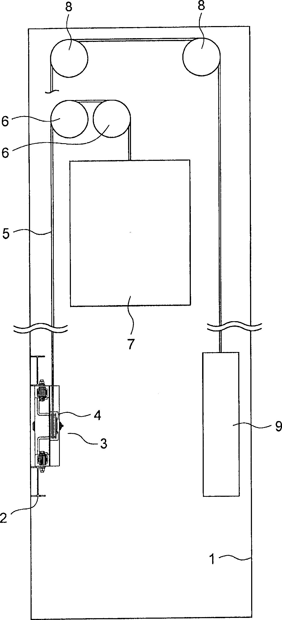
[0019] figure 1 It is a configuration diagram showing a state in which the hoisting machine 3 according to Embodiment 1 of the present invention is installed in the hoistway 1 .

[0020] In this elevator, a hoisting machine 3 is fixed to a wall surface of a hoistway 1 via beams 2 . A rope 5 is wound around a sheave 4 of the traction machine 3 . One end portion of the rope 5 is connected to the car 7 via the car-side return sheave 6 . The other end of the rope 5 is connected with the counterweight 9 through the counterweight side reversing sheave 8 .

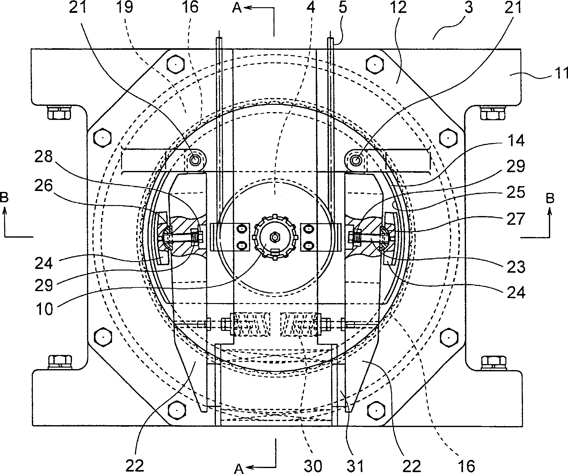
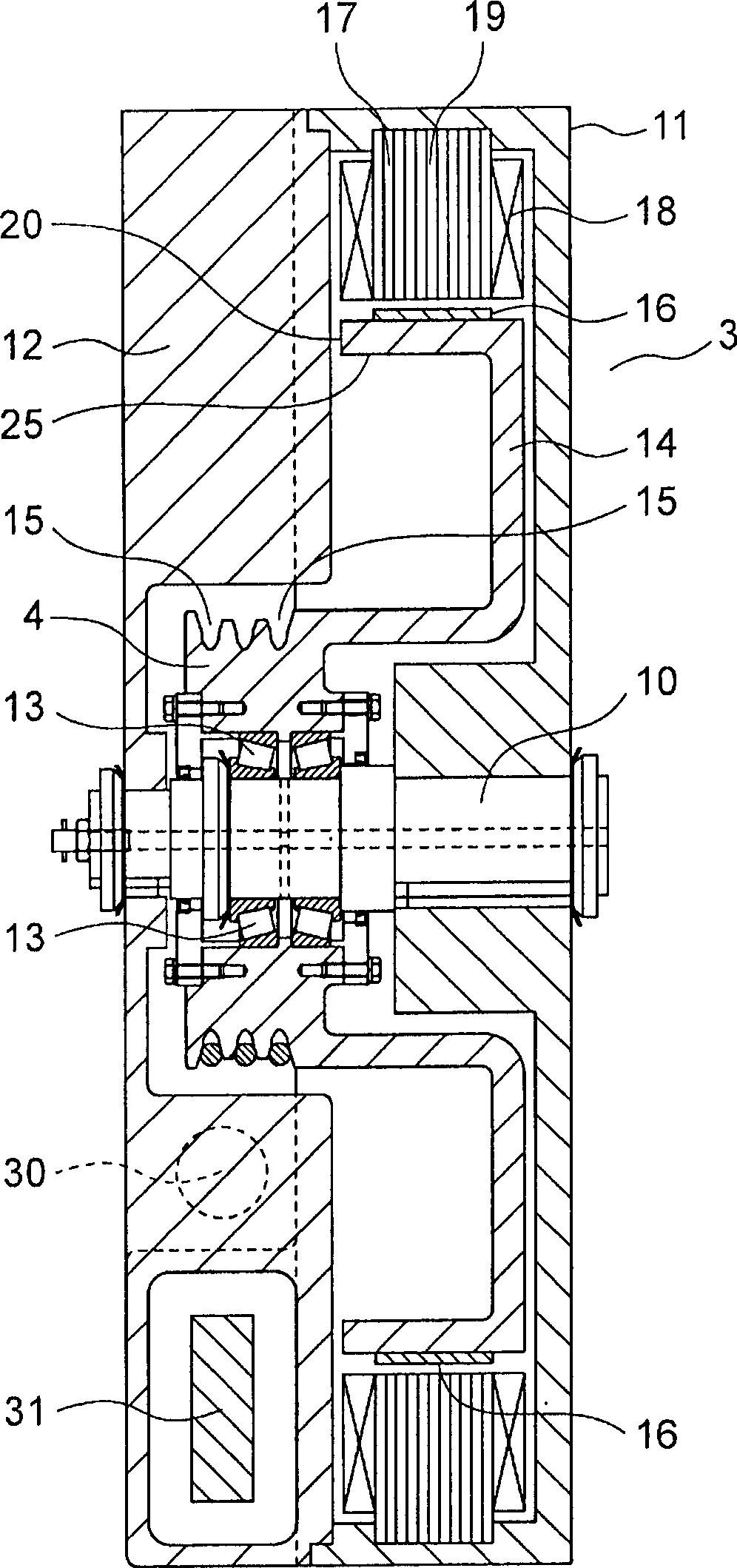
[0021] figure 2 yes means figure 1 The front view of the traction machine 3 in, image 3 yes figure 2 The traction machine 3 in is cut along the arrow direction cross-sectional view of A-A line.

[0022] In this hoisting machine 3, the opposing motor-side housing 11 and brake-side housing 12 are fixed to each other. A fixed shaft 10 is fixed to the centers of the motor side housing 11 and the brake side housing 12 . Th...


PUM


Abstract

A hoist for an elevator, wherein a brake side housing is fixed, oppositely to each other, to a motor side housing in which a motor is installed. A pulley is rotatably mounted on a fixed shaft fixed through the brake side housing and the motor side housing. One end parts of a pair of brake arms are rotatably fitted to the brake side housing, and brake shoes in slidable contact with the braking surface of a brake drum are mounted on the brake arms. A braking spring energizing the pair of brake arms in a mutually separating direction is installed in the brake side housing between the pair of brake arms. An electromagnet rotating the brake arms by attracting the other end parts of the pair of brake arms against the elastic force of the braking spring is installed in the brake side housing between the other end parts of the pair of brake arms.

Description

technical field [0001] The present invention relates to a traction machine for an elevator, which is used to drive a rope to raise and lower a car. Background technique [0002] As a conventional hoisting machine for an elevator, there is known a hoisting machine in which a brake device including a brake arm and a brake shoe is arranged on the back side of a sheave (for example, refer to Patent Document 1). [0003] Patent Document 1: Japanese Patent Laid-Open No. 2000-289954 [0004] However, in the case of such a traction machine for an elevator, when both the sheave and the braking device are to be maintained and inspected separately, maintenance and inspection must be performed from both sides. When between the wall of the car and the lifting car, for example, in the wall area facing the sheave, a space for maintenance and inspection protruding to the opposite side of the car must be provided. [0005] In addition, if there is no such space, the wear amount of the groo...

Claims


Application Information

Patent Timeline
Patent Type & Authority Applications(China)
IPC IPC(8): B66B11/08
CPCB66D5/08B66D5/30
Inventor 饭田康雅
Owner MITSUBISHI ELECTRIC CORP
Why Eureka
Try Eureka