
Column-beam attaching tectosome of architecture and method of attaching the same

A technology for buildings and structures, which is applied in the direction of building construction and construction, and can solve problems such as complex operations, large structures, and inability to transport on roads, so as to save concrete pouring operations and reduce on-site operations.

Active Publication Date: 2006-08-23
SUMITOMO MITSUI CONSTR CO LTD
View PDF4 Cites 10 Cited by
  • Summary
  • Abstract
  • Description
  • Claims
  • Application Information

AI Technical Summary

Problems solved by technology

As a result, when manufacturing precast concrete members in factories, it is necessary to classify (differentiate) the strength of concrete, which complicates the work
[0014] In the technology described in Patent Document 4, although the column-beam connection is prefabricated, it is necessary to perform on-site concrete pouring work on the connection between the connecting beam members.
In addition, when the beam member is made into a cross-shaped structure in advance, even if it can be manufactured in a factory, the overall volume of the structure is large, so there is a problem that it cannot be transported on the road due to size restrictions.

Method used


Image

  • Column-beam attaching tectosome of architecture and method of attaching the same
  • Column-beam attaching tectosome of architecture and method of attaching the same
  • Column-beam attaching tectosome of architecture and method of attaching the same

Examples


Embodiment Construction

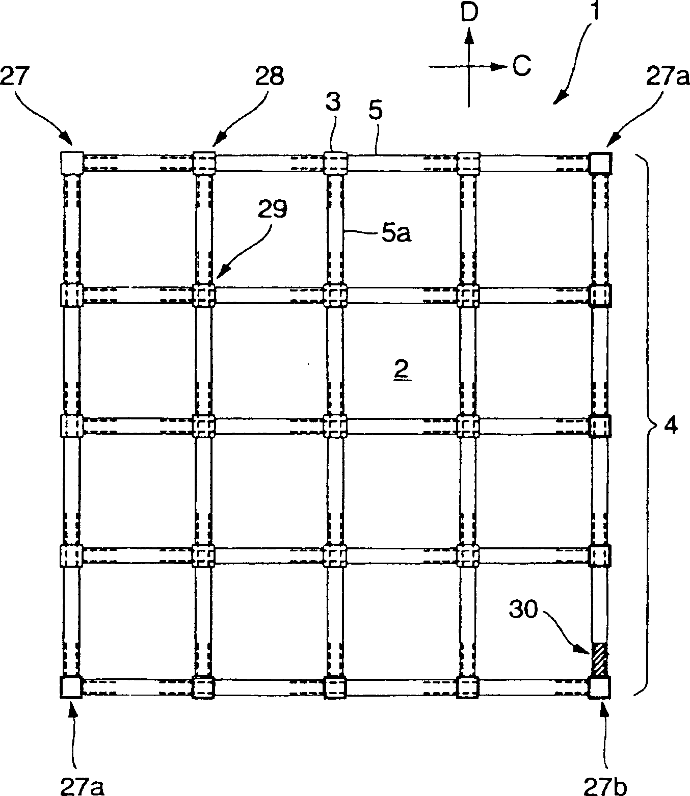
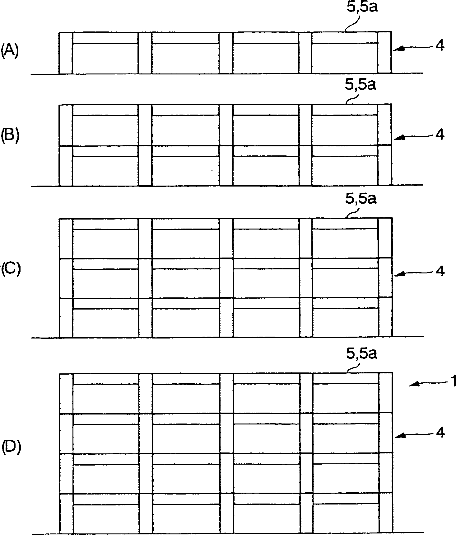
[0037] In the column-beam connection structure of the following embodiment, the column connection part is formed integrally with the precast concrete column, and the several through-holes are formed in the horizontal direction in this column connection part. In addition, a precast concrete beam is installed horizontally on the column connection part, and a plurality of connecting steel bars for the beam protrude from one end surface of the precast concrete beam in the longitudinal direction, and a plurality of beam joints are provided inside the other end surface. part.

[0038] Furthermore, the beam connecting steel bar of the precast concrete beam is passed through the through hole of the column connection part of the precast concrete column, and inserted into the beam joint part of the adjacent precast concrete beam that has been installed, thereby connecting the precast concrete beam through the column connection part. The concrete beams are connected to each other.

[00...


PUM


Abstract

The invention provided a column-beam joint structure of buildings in which operations in each process from the manufacture of columns made of PCa and beams made of PCa, their transport, and their assembly in the field can be consistently and easily performed without restraints and concrete placing operations can be omitted by completely pre-casting the column-beam joint structure. In the column-beam joint structure 4, horizontal through holes 7 are formed in a column joint section 6 of a column 3 made of PCa, connection reinforcing bars 10 for beams are protruded from faces 9a on one side of girders 5 and 5a, and a plurality of sleeves 12 for beams are provided for the inside of faces 9b on the other side. By passing the connection reinforcing bars for beams of the girders through the through holes of the column joint section of the column made of PCa and inserting them in the sleeves for beams of adjacent, already placed girders, girders are joined to each other via the column joint section.

Description

technical field [0001] The present invention relates to a column-beam connection structure and a connection method of buildings such as collective houses. Background technique [0002] In a building such as a multi-story building, its column-beam connection structure (skeleton structure) is composed of a plurality of precast concrete columns and precast concrete beams erected between adjacent precast concrete columns. [0003] For example, Patent Document 1 (JP-A-6-93656) describes a frame composed of prefabricated reinforced concrete columns (precast concrete columns) and prefabricated reinforced concrete beams (precast concrete beams). In this frame, an in-situ concrete layer is formed on the ends of the column main bars and the like. [0004] In Patent Document 2 (Japanese Unexamined Patent Publication No. 2001-279811), beam connecting ribs are penetrated and installed at the connecting portion of precast concrete column members, and beam main ribs are protruded from the...

Claims


Application Information

Patent Timeline
IPC IPC(8): E04B1/20
Inventor 梅木俊毅松本启二菅谷和人小坂英之贯洞觉
Owner SUMITOMO MITSUI CONSTR CO LTD
Learn More