
Dead zone protecting circuit of electronic prospecting signal transmitter

A dead zone protection, electrical exploration technology, applied in electrical/magnetic exploration, logic circuits, logic circuits using specific components, etc. The effect of improving reliability, protecting normal work and reducing failure rate

Inactive Publication Date: 2006-08-16
CENT SOUTH UNIV
View PDF0 Cites 4 Cited by
  • Summary
  • Abstract
  • Description
  • Claims
  • Application Information

AI Technical Summary

Problems solved by technology

However, the reliability of this solution is low. There are two reasons for this: first, the IPMs produced by different companies have different requirements for the length of the dead zone; It will lead to a large shutdown time required by the transmitter, and once this time exceeds the dead time set by the control software, it will still cause a short circuit in the power supply circuit, causing the transmitter to start a protection action, or even burn the device

Method used


Image

  • Dead zone protecting circuit of electronic prospecting signal transmitter
  • Dead zone protecting circuit of electronic prospecting signal transmitter

Examples


Embodiment Construction

[0011] The present invention will be further described below in conjunction with the accompanying drawings.

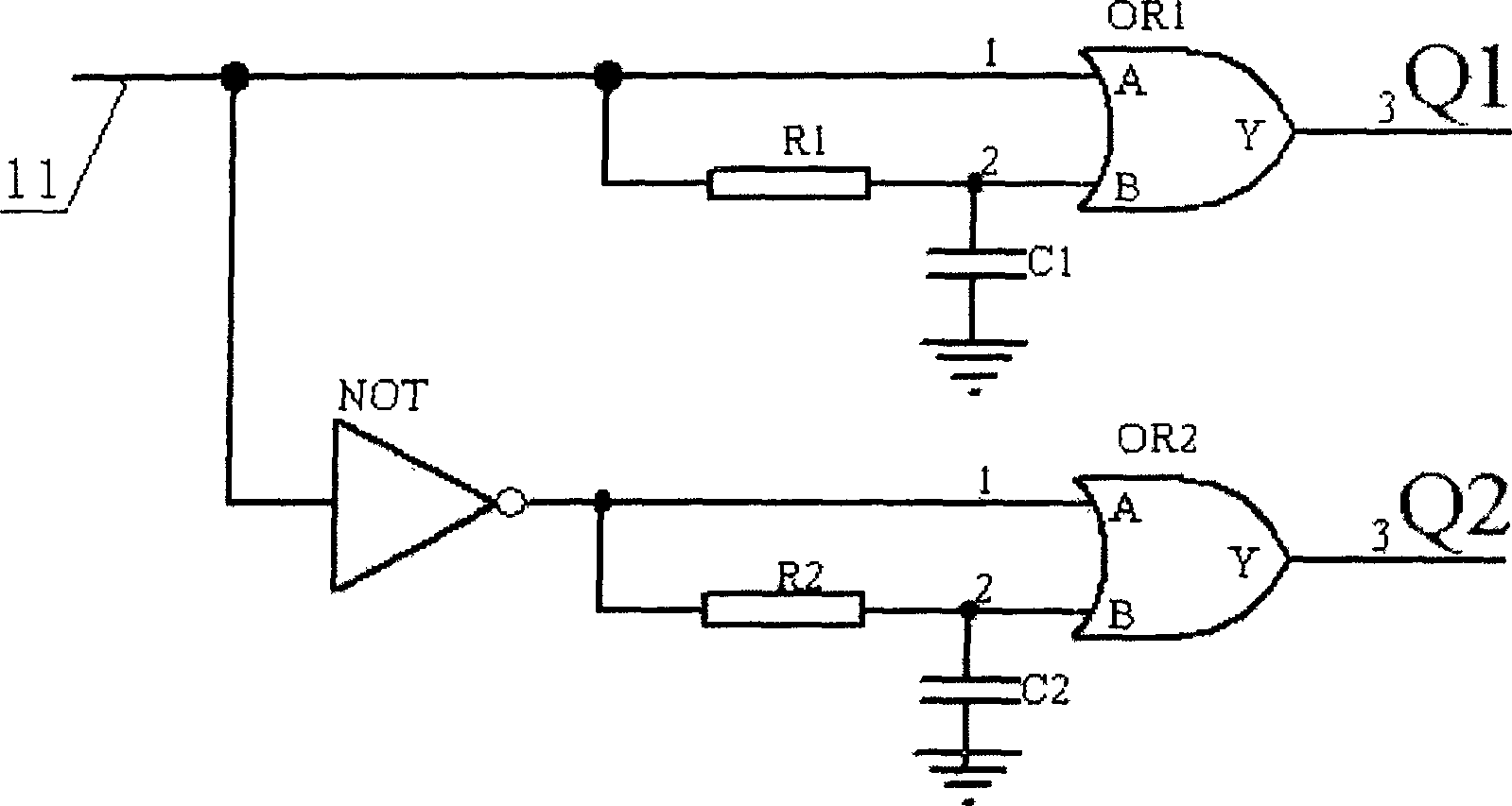
[0012] refer to figure 1 , this embodiment includes an OR gate OR1 and an OR gate OR2, the pin 1 of the OR gate OR1 is directly connected to the control signal input line 11, and the pin 2 of the OR1 is connected to the control signal input line 11 after being connected in series with the resistor R1, The pin 2 of OR1 is grounded through the capacitor C1; the control signal input line 11 is also connected with the pin 1 of the OR gate OR2 through the NOT gate, and the pin 2 of OR2 is connected with the NOT gate through the resistor R2 and grounded through the capacitor C2.

[0013] The specific working process is as follows:

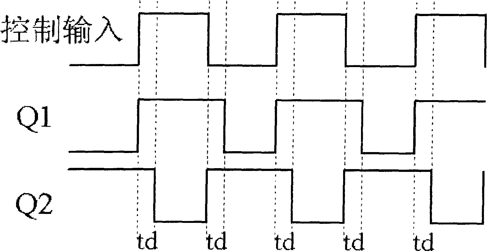
[0014] When the control signal changes from low to high, pin 1 of OR gate OR1 becomes high at the same time, therefore, OR gate OR1 outputs high level; pin 2 is delayed by resistor R1 and capacitor C1, so it takes a while to It will become high...


PUM


Abstract

The invention consists of resistor, capacitor and OR gate. One of OR gate pins is connected to the control signal inputting line, and the other one is connected to the control signal inputting line after connected to said resistor in series and is grounded through said capacitor. After adding dead area protective circuit, the electrical prospecting transmitter has a required dead area time not relating to the control waveform. With only given control signals, the required dead area time can be generated by the invention.

Description

technical field [0001] The invention relates to a dead zone protection circuit of an electrical prospecting signal transmitter. Background technique [0002] For high-power electrical prospecting transmitters, due to their relatively large transmission current, there will be a certain delay time from when the controller sends the shutdown control signal to when the IPM (Intelligent Power Module) switching device is completely turned off, that is, the inverse The variable device itself has problems such as turn-off delay, and because the field working conditions are more complicated, its load is variable according to different power supply conditions, especially the inductive load, which has a great impact on the turn-off time of the IPM, so it often occurs It leads to false conduction, that is, the upper and lower two-phase switches are turned on at the same time, causing a short circuit in the sending circuit and easily burning the device. At pres...

Claims


Application Information

Patent Timeline
Patent Type & Authority Applications(China)
IPC IPC(8): H03K19/173H03K19/00G01V3/00
Inventor 陈儒军刘石何继善颜良
Owner CENT SOUTH UNIV
Learn More