Variable displacement compressor

A compressor and capacity technology, applied in the direction of liquid variable capacity machinery, variable capacity pump components, mechanical equipment, etc., can solve problems such as hindering the starting performance of compressors

Inactive Publication Date: 2006-08-16
TOYOTA IND CORP
View PDF1 Cites 4 Cited by
  • Summary
  • Abstract
  • Description
  • Claims
  • Application Information

AI Technical Summary

Problems solved by technology

As a result, the capacity of the compressor can only be high enough after a considerable delay, hampering the compressor's starting performance

Method used


Image

  • Variable displacement compressor
  • Variable displacement compressor
  • Variable displacement compressor

Examples


Embodiment Construction

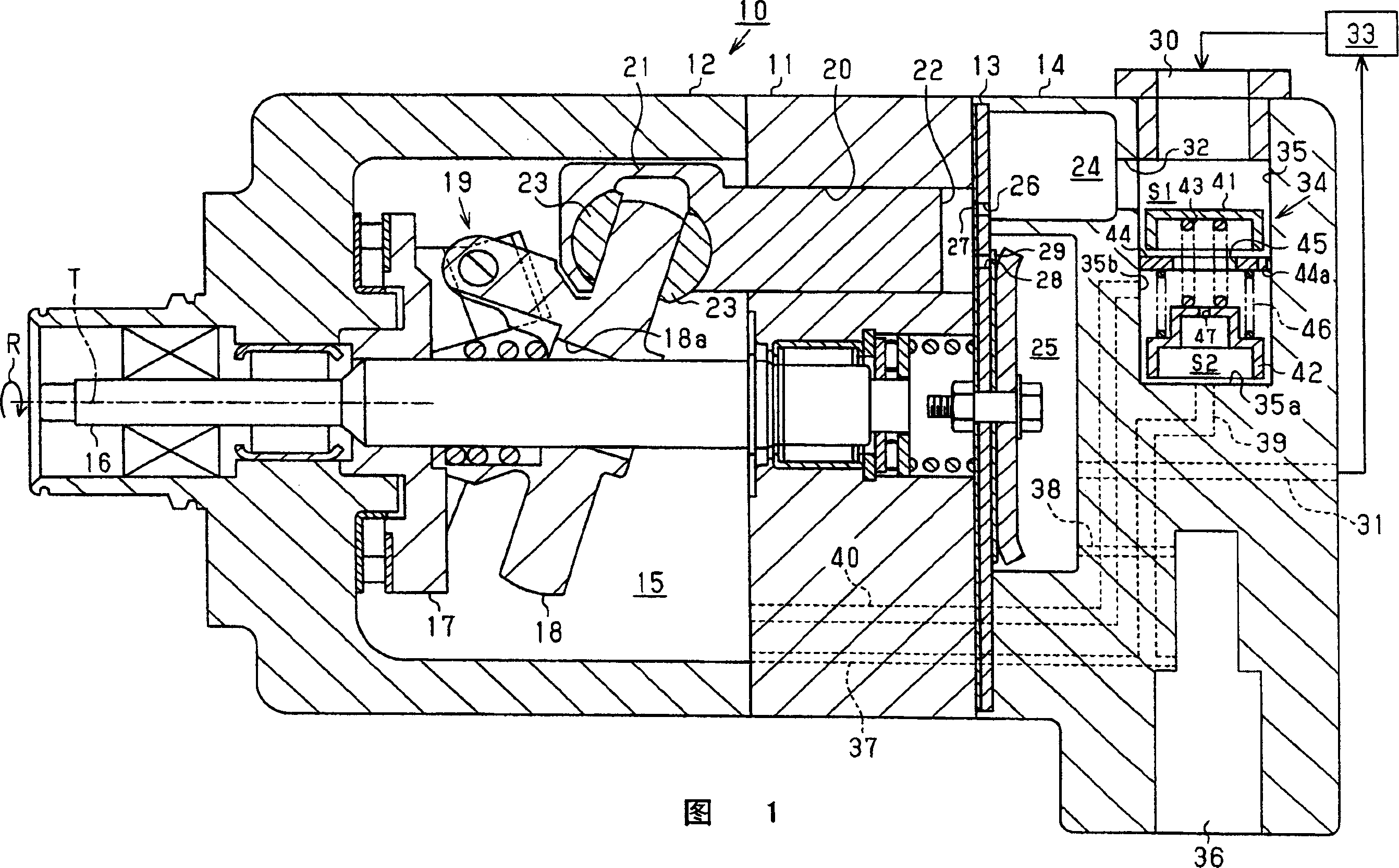
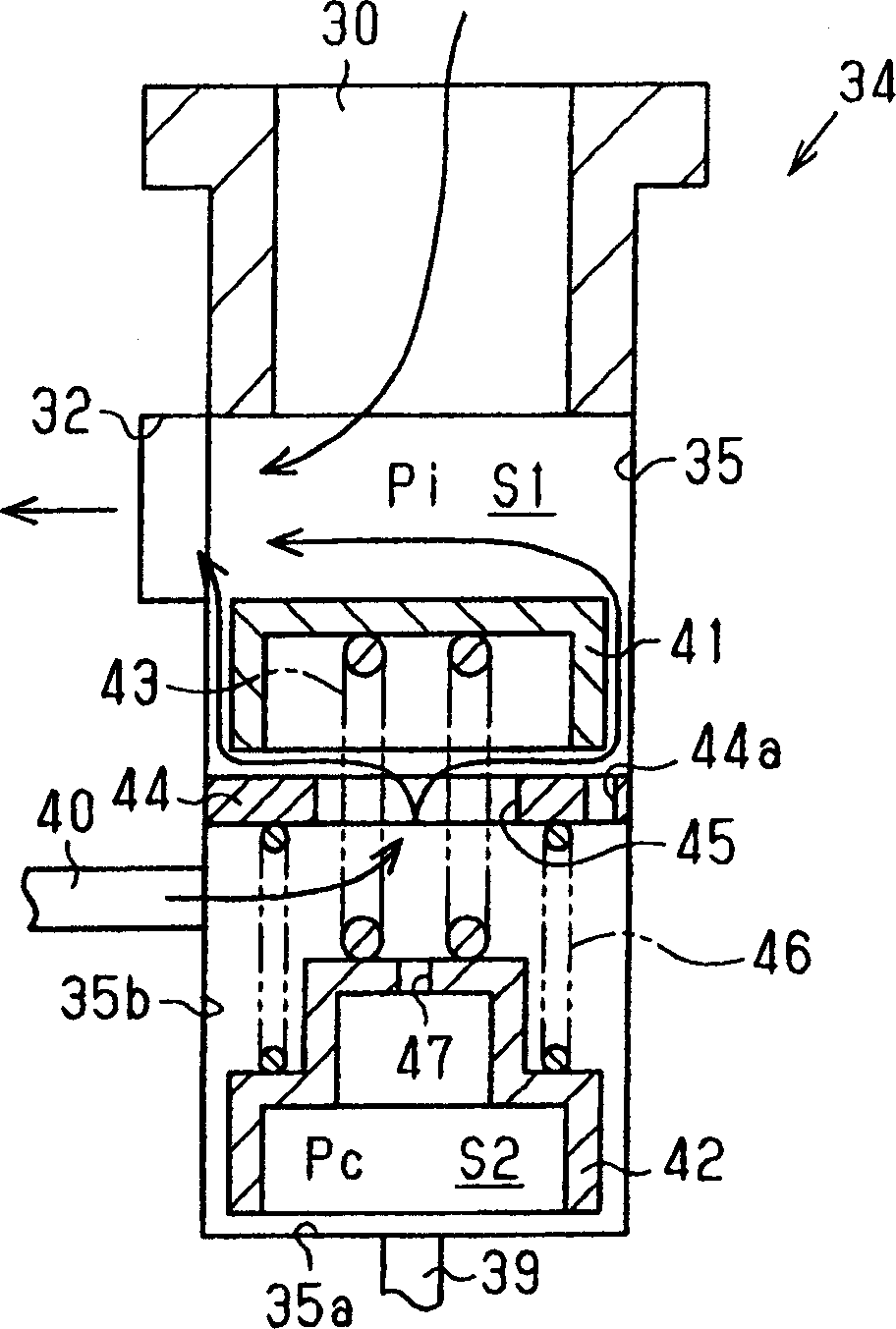
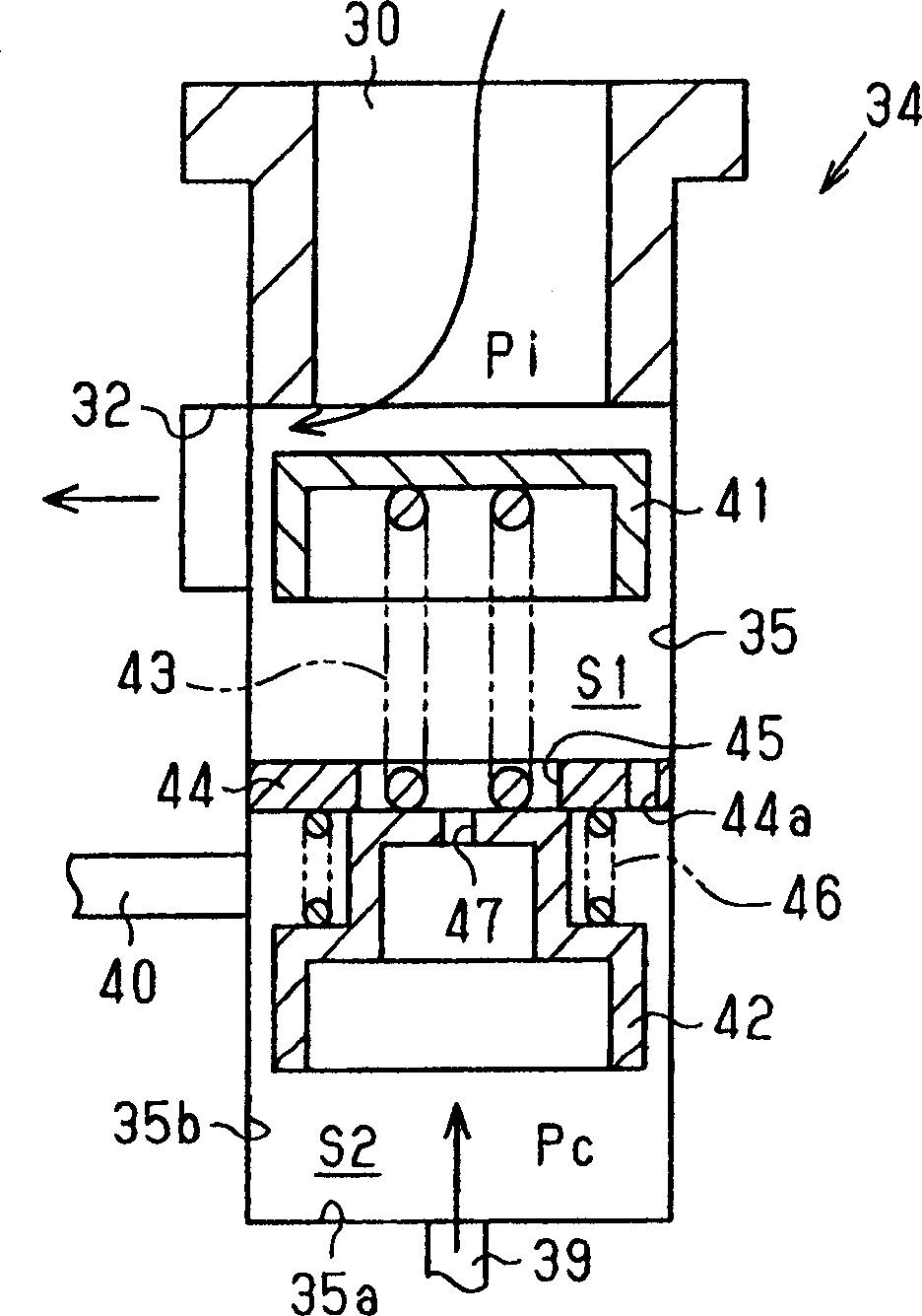
[0013] Referring to FIGS. 1-3, a clutchless type variable capacity compressor in accordance with an embodiment of the present invention will now be described.

[0014] Fig. 1 is a longitudinal sectional view showing a compressor 10 of the illustrated embodiment. The front portion of compressor 10 is shown on the left in FIG. 1 and the rear portion of compressor 10 is shown on the right of the figure. As shown in FIG. 1 , the compressor 10 includes a cylinder block 11 , a front housing member 12 , a valve housing member 13 and a rear housing member 14 . The front housing element 12 is fixedly connected to the front end of the cylinder block 11 . The rear housing element 14 is fixedly connected to the rear end of the cylinder 11 . The valve housing element 13 is arranged between the cylinder block 11 and the rear housing element 14 . The housing of the compressor 10 is defined by a cylinder block 11 , a front housing element 12 and a rear housing element 14 .

[0015] A cran...


PUM


Abstract

Refrigerant gas is introduced into the suction chamber through the suction line. Refrigerant gas can flow from the crank chamber to the suction chamber through the outlet line. The opening degree regulating valve (34) has a first valve body for adjusting the opening degree of the suction pipeline and a second valve body for adjusting the opening degree of the outlet pipeline. The first valve body and the second valve body are connected to each other. The first valve body moves in such a way that when the difference between the pressure in the suction chamber and the pressure in the crank chamber decreases, the opening of the suction line increases; when the difference between the pressure in the suction chamber and the pressure in the crank chamber When the difference between them increases, reduce the opening of the suction line. Therefore, variation in gas pressure is reliably suppressed while maintaining good start performance of the compressor.

Description

technical field [0001] The present invention relates to a variable capacity compressor that changes the stroke of a piston accommodated in a cylinder bore by adjusting the pressure in a crank chamber. Background technique [0002] The variable capacity compressor reciprocates the piston in the cylinder bore by the rotation of the drive shaft. This compresses the gas within the compression chamber and expels the gas from the compression chamber. The capacity of the compressor can be changed by changing the stroke of the piston. When the gas flow rate of the compressor is relatively reduced, the amount of gas passing through the suction valve is correspondingly reduced. This causes the suction valve to vibrate self-induced in a free vibration region where the suction valve avoids contact with the stop. This vibration of the suction valve changes the pressure of the gas. The pressure change of the gas is then transmitted to the evaporator of the external refrigeration circu...

Claims


Application Information

Patent Timeline
Patent Type & Authority Applications(China)
IPC IPC(8): F04B49/06F04B39/00F04B39/10F04B27/08
CPCF04B27/1804F04B49/225F04B2027/1831F04B2027/1845F04B2027/1859F04B2027/1881F04B27/1018F04B27/1036F05B2210/12F05B2210/14Y10S417/00
Inventor 太田雅树中山治金井明信山之内亮人
Owner TOYOTA IND CORP
Why Eureka
Try Eureka