Dust and debris extraction apparatus for power tool

A technology for electric tools and suction equipment, applied in metal processing equipment, manufacturing tools, striking tools, etc., can solve the problems of time-consuming, easy to break, and cumbersome.

Inactive Publication Date: 2006-08-16
GMCA PTY LIMITED
View PDF0 Cites 9 Cited by
  • Summary
  • Abstract
  • Description
  • Claims
  • Application Information

AI Technical Summary

Problems solved by technology

While this dust extraction system is known to work successfully, it also tends to be fragile, parts are easily damaged, and routine assembly of the different parts is time consuming and cumbersome for the user

Method used


Image

  • Dust and debris extraction apparatus for power tool
  • Dust and debris extraction apparatus for power tool
  • Dust and debris extraction apparatus for power tool

Examples


Embodiment Construction

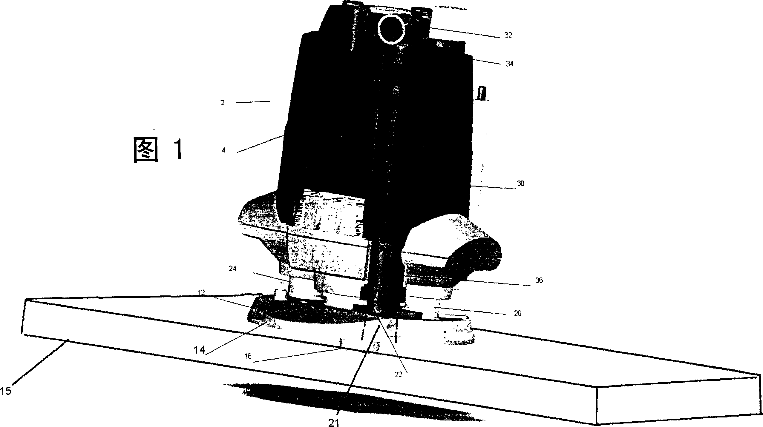
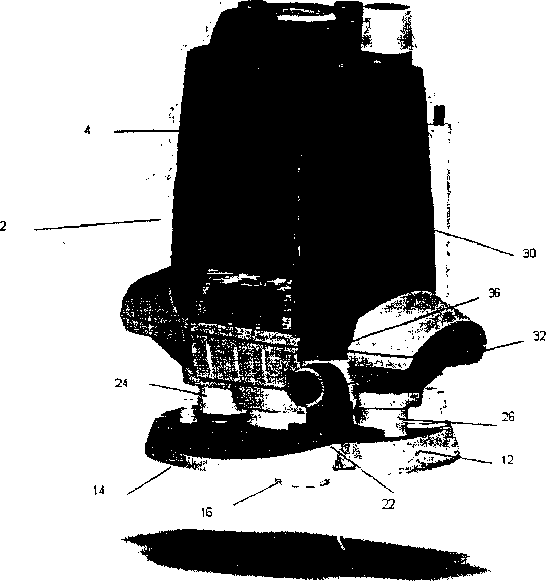
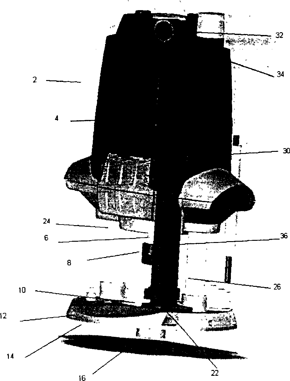
[0027] Referring first to Figures 1-4, there is shown a router 2 according to one embodiment of the present invention. The router 2 includes a body 4 in which a motor (not shown) is accommodated. A motor is connected to rotate a shaft 6 which is selectively connected to any one of a set of router heads 8 . The shaft and router extend through opening 10 in base 12 . In use the underside 14 of the base 12 lies on the plane of a workpiece 15 which is to be subjected to a router operation, which is only shown in FIG. 1 . The underside of the base generally includes a cavity 16 adjacent to the router so that dust and debris generated during operation enters the cavity 16 and then passes through an opening or hole 21 (shown in dotted lines only in FIG. 1 ). The hole), the opening or hole 21 passes through the base from the underside of the base to the upper side of the base and the collar 22. The collar 22 serves as connecting means for connecting the first or second dust and deb...


PUM


Abstract

The invention relates to a power tool such as a router which is provided to perform an operation on a work piece. The tool includes dust extraction apparatus to allow dust and debris to be removed from the location at which the work is performed and part of the extraction apparatus is movable between storage and in-use positions. When said part is moved to a storage position, an alternative dust extraction passage may be fitted in to the port or aperture. Typically, the part which is movable can be telescopically movable or alternatively, can be provided of a flexible member so as to be moved between extended and retracted positions.

Description

technical field [0001] The present invention relates to a power tool with means for removing dust and debris from the location where the power tool is used to perform a cutting, perforating, or drilling operation on a workpiece. The device finds particular application in power tools in the form of routers, which generally include a motor in a housing mounted on first and second slide bars. The motor is used to drive a router tool that extends from one end of the frame and moves onto and across the workpiece to perform a router operation on the plane of the workpiece. However, it is to be noted that while the present invention applies to routers, the dust and debris removal apparatus may also be used on other forms of power tools. Background technique [0002] One problem with power tools is that as they perform the necessary operations on the workpiece, they create dust and debris. If suction equipment is not provided to remove this dust and debris from the work area, the ...

Claims


Application Information

Patent Timeline
Patent Type & Authority Applications(China)
IPC IPC(8): B25F5/00B25D17/14B27C1/00B27C1/14B23Q11/00
CPCY10T408/50Y10T409/306608B23Q11/0046Y10T409/304088
Inventor 迈克·沃尔德伦
Owner GMCA PTY LIMITED
Why Eureka
Try Eureka