
Video-frequency encoding-rate controlling method

A video coding and rate control technology, applied in the field of multimedia communication, can solve the problem that the video coding rate cannot be accurately controlled in the interval adjacent to the target rate, etc.

Inactive Publication Date: 2006-08-09
SNAPTRACK
View PDF0 Cites 11 Cited by
  • Summary
  • Abstract
  • Description
  • Claims
  • Application Information

AI Technical Summary

Problems solved by technology

[0030] The purpose of the present invention is to provide a method for video coding rate control to overcome the problem that the video coding rate cannot be accurately controlled in the interval of the target rate in the prior art

Method used


Image

  • Video-frequency encoding-rate controlling method
  • Video-frequency encoding-rate controlling method
  • Video-frequency encoding-rate controlling method

Examples


Embodiment Construction

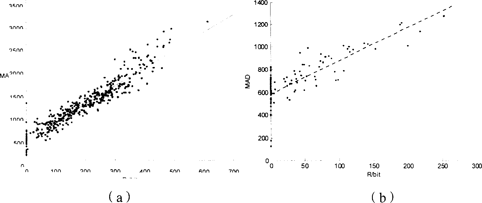
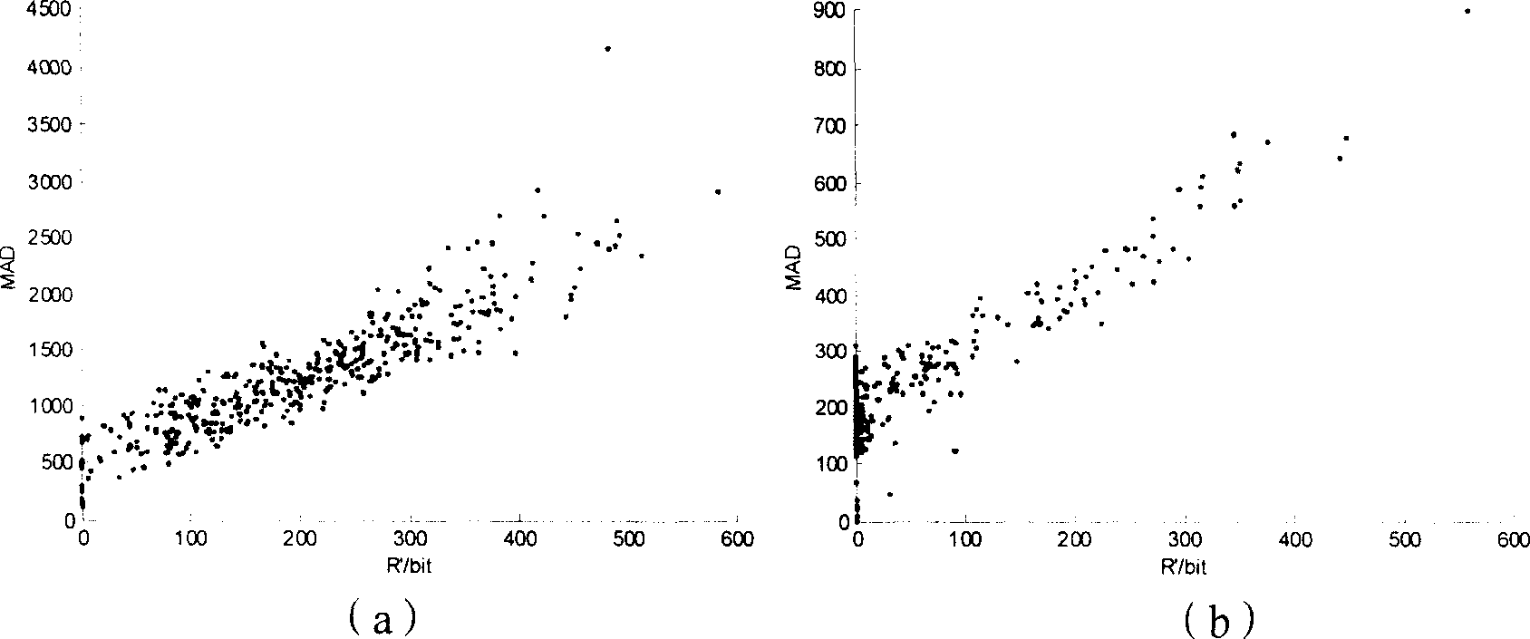
[0099] The core of the present invention is to establish a secondary rate-distortion model according to the rate-distortion theoretical model of the information source with Laplace distribution statistical characteristics, and perform video coding rate control according to the secondary rate-distortion model.

[0100] The technical solution provided by the present invention will be further described below based on the core idea of ​​the present invention.

[0101] If the source has the statistical characteristics of Laplace distribution, the logarithmic form of the rate-distortion equation can be expanded into a Taylor series to obtain the following expression:

[0102] R ( D ) = ln ( 1 αD ) = ( 1 αD - 1 ) ...


PUM


Abstract

Main points of the invention are as following: using rate distortion theory of message source of possessing statistic characteristics of Laplace distribution to build secondary rate distortion model; using secondary rate distortion model to control video encoding rate. Secondary rate distortion model built in the invention is better accorded with real characteristics of rate distortion of video message source. The invention makes encoding output rate of video sequence closer to given channel bandwidth. The invention raises accuracy for controlling video encoding rate, and raises video encoding quality. Advantages are: better performance of rate distortion, applicable to real time multimedia communication and stream media through network.

Description

technical field [0001] The invention relates to the field of multimedia communication, in particular to a method for video coding rate control. Background technique [0002] Video coding rate control is a research hotspot in video coding. Whether it is in the early H.261, MPEG-1, or in the current mainstream H.263 / H.263+ / H.263++, MPEG-2 / MPEG-4, or in the latest video coding rate control In H.264, all are very important. Only by solving the problem of video coding rate control well, can the video media stream be transmitted most effectively on the channel with a given rate. [0003] By optimizing a series of encoding parameters, video encoding rate control can enable the video encoder to obtain the best encoding quality under a given rate limit, and at the same time control the encoding bit rate more accurately near the target rate to meet the channel bandwidth and decoding requirements. End buffer size limit. [0004] QP (Quantization Parameter) and rate-distortion model ...

Claims


Application Information

Patent Timeline
IPC IPC(8): H04N7/24
Inventor 罗忠王静万帅常义林杨付正
Owner SNAPTRACK
Learn More