Vortex rotary compressor

A scroll compressor and compressor technology, applied in the direction of rotary piston machinery, rotary piston pump, rotary piston/swing piston pump components, etc., can solve the problem of high installation accuracy, heavy mass, exhaust temperature Advanced problems, to achieve the effect of stable operation, simple structure and low noise

Inactive Publication Date: 2006-08-02
蒋宗传 +1
View PDF0 Cites 3 Cited by
  • Summary
  • Abstract
  • Description
  • Claims
  • Application Information

AI Technical Summary

Problems solved by technology

Some technologies use the method of combining the number of turns to change the profile to improve the compression ratio, and the result is only a small increase in the compression ratio
[0004] 2. The inspiratory volume is small
The dynamic and static scroll should be milled in the machining center. Due to the limitation of the machining size of the machine tool and the length of the tool, the size of the scroll is limited, making it difficult for the scroll compressor to be used in occasions with large volume requirements.
[0005] 3. The process from the suction process to the compression and exhaust process is carried out under adiabatic conditions. When the compression force is relatively high, the exhaust temperature will be high, the thermal deformation of the parts will be large, and more power and energy will be consumed.
The disadvantage of the cross ring is its heavy mass and large inertial force when the size is large
The disadvantage of the small crankshaft is its high installation accuracy and its inability to self-compensate

Method used


Image

  • Vortex rotary compressor
  • Vortex rotary compressor
  • Vortex rotary compressor

Examples


Embodiment Construction

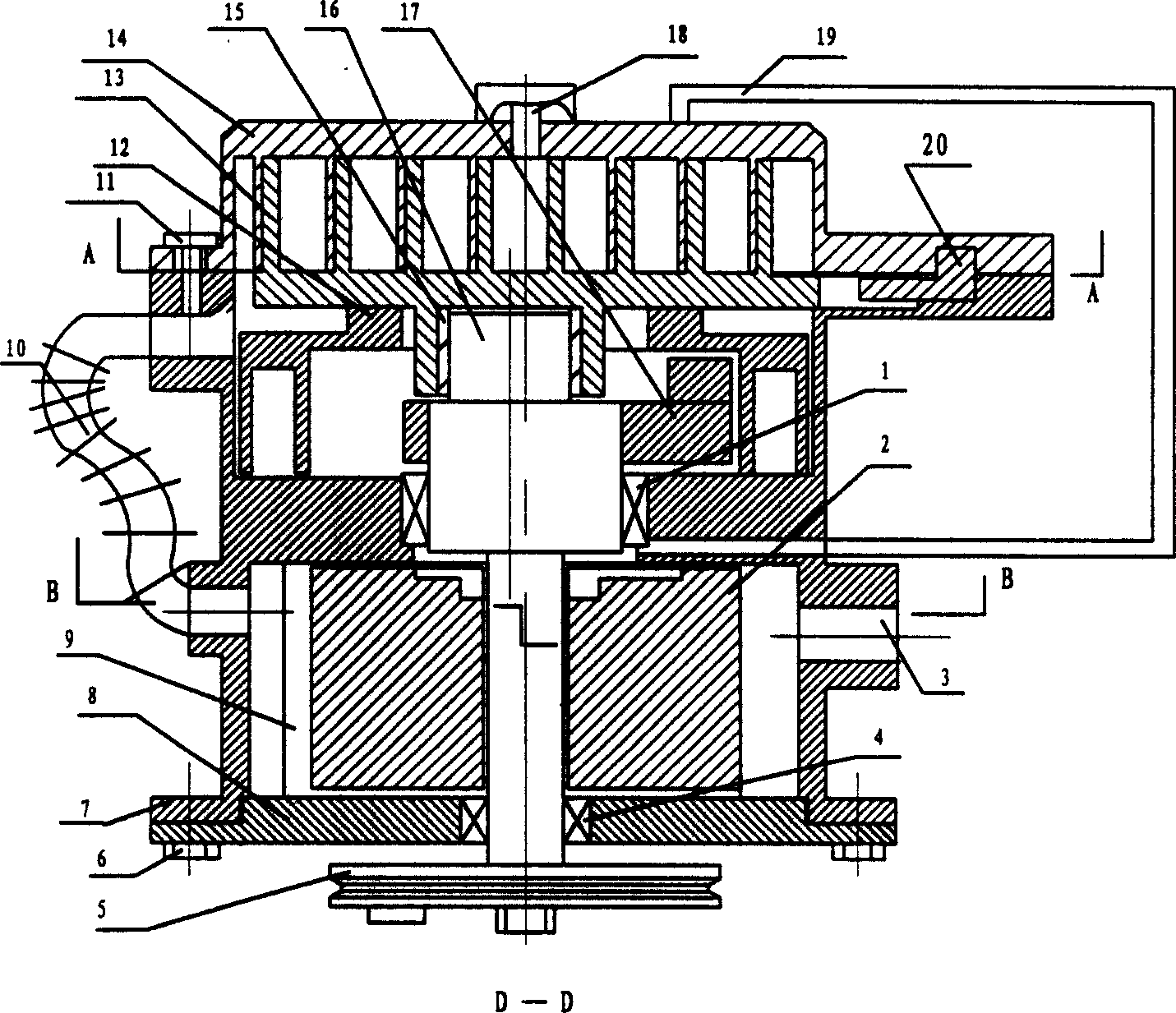
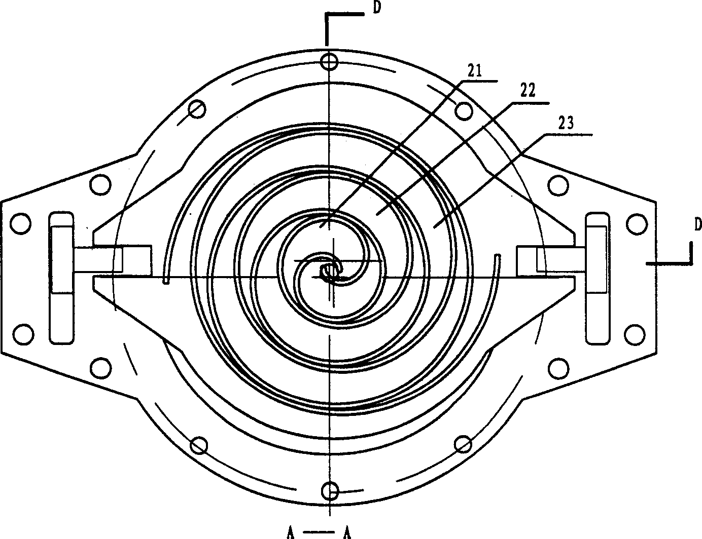
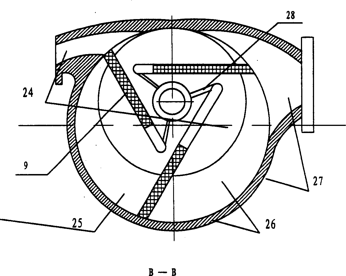
[0020] Such as Figure 1 ~ Figure 3 As shown, the scroll rotary compressor of the present invention has a main bearing 1 supporting a main shaft 16, an auxiliary bearing 4, and an orbiting scroll bearing 15, and a belt pulley 5, a main balancer 17, a fuselage 7 and an end cover are installed on the main shaft 8 are connected by screws 6, the lower end of the main shaft 16 is equipped with the rotor 2 contained in the fuselage 7, the rotor 2 is equipped with a sliding plate 9, the upper end of the main shaft 16 is equipped with a movable scroll 13, and the static vortex matched with the movable scroll 13 The roll 14 is fastened to the fuselage 7 with bolts 11 . In this way, the scroll and rotary compressors are connected in series.

[0021] The scroll rotary compressor of the present invention is equipped with T-shaped blocks 20 symmetrically on both sides of the movable scroll 13 and the static scroll 14. A part of the T-shaped blocks 20 is slidingly fitted with the chute of ...


PUM


Abstract

The vortex rotary compressor includes a compressor body; a vortex compressor comprising static scroll and movable scroll inside the compressor body, main shaft driving the movable scrolls to rotate, and limiting block to avoid the rotation of the movable scroll; and a sliding vane compressor coaxial with the vortex compressor. The vortex compressor has inlet connected to the outlet inlet of the sliding vane compressor, and compressing cavity communicated with the flow channel inside the compressor body, the flow channel inside the rotor of the sliding vane compressor and the sliding vane slot inside the sliding vane of the sliding vane compressor. The vortex rotary compressor has the characteristics of both vortex compression and rotary sliding vane compression, greatly raised gas compression ratio and displacement amount and expanded use range.

Description

technical field [0001] The invention relates to a rotary piston variable displacement pump suitable for elastic fluid, in particular to a combined scroll and rotary vane compressor. The present invention utilizes the advantages of the two compressors to combine them into an integrated novel scroll rotary compressor. It has the characteristics of scroll compression and rotary vane compression in a single body. Background technique [0002] At present, the scroll compressor has been widely used in the industrial and civil product fields of refrigeration air and gas compression due to its advantages of high reliability, low noise, and high energy-saving efficiency. Its working principle is that there are a pair of intermeshing scrolls in the scroll compressor. A moving scroll is called a moving scroll, and a stationary scroll is called a static scroll. The movable scroll rotates in a plane relative to the stationary scroll, thereby forming multiple compression chambers with ...

Claims


Application Information

Patent Timeline
IPC IPC(8): F04C23/00F04C18/02F04C18/344F04C29/04
Inventor 蒋宗传蒋兴振
Owner 蒋宗传
Why Eureka
Try Eureka