
Welded golf club head

A golf club head and club head technology, applied to golf balls, golf clubs, rackets, etc., can solve time-consuming surface processing steps, complex structure of the ball hitting panel and club head body, unfavorable manufacturing and rapid pre-assembly, etc. problem, achieve the effect of increasing welding quality and avoiding incomplete welding

Inactive Publication Date: 2006-08-02
FUSHENG IND CO LTD
View PDF0 Cites 2 Cited by
  • Summary
  • Abstract
  • Description
  • Claims
  • Application Information

AI Technical Summary

Problems solved by technology

[0011] However, the disadvantage of the above-mentioned welded joint structure is that the supporting rod and the locking gap cause the structure of the ball striking panel and the head body to be complicated, which is not conducive to manufacturing and quick pre-assembly
After welding, time-consuming and relatively extensive surface processing steps are also required to remove the remaining material of the support rod and the snap notch

Method used


Image

  • Welded golf club head
  • Welded golf club head
  • Welded golf club head

Examples


Embodiment Construction

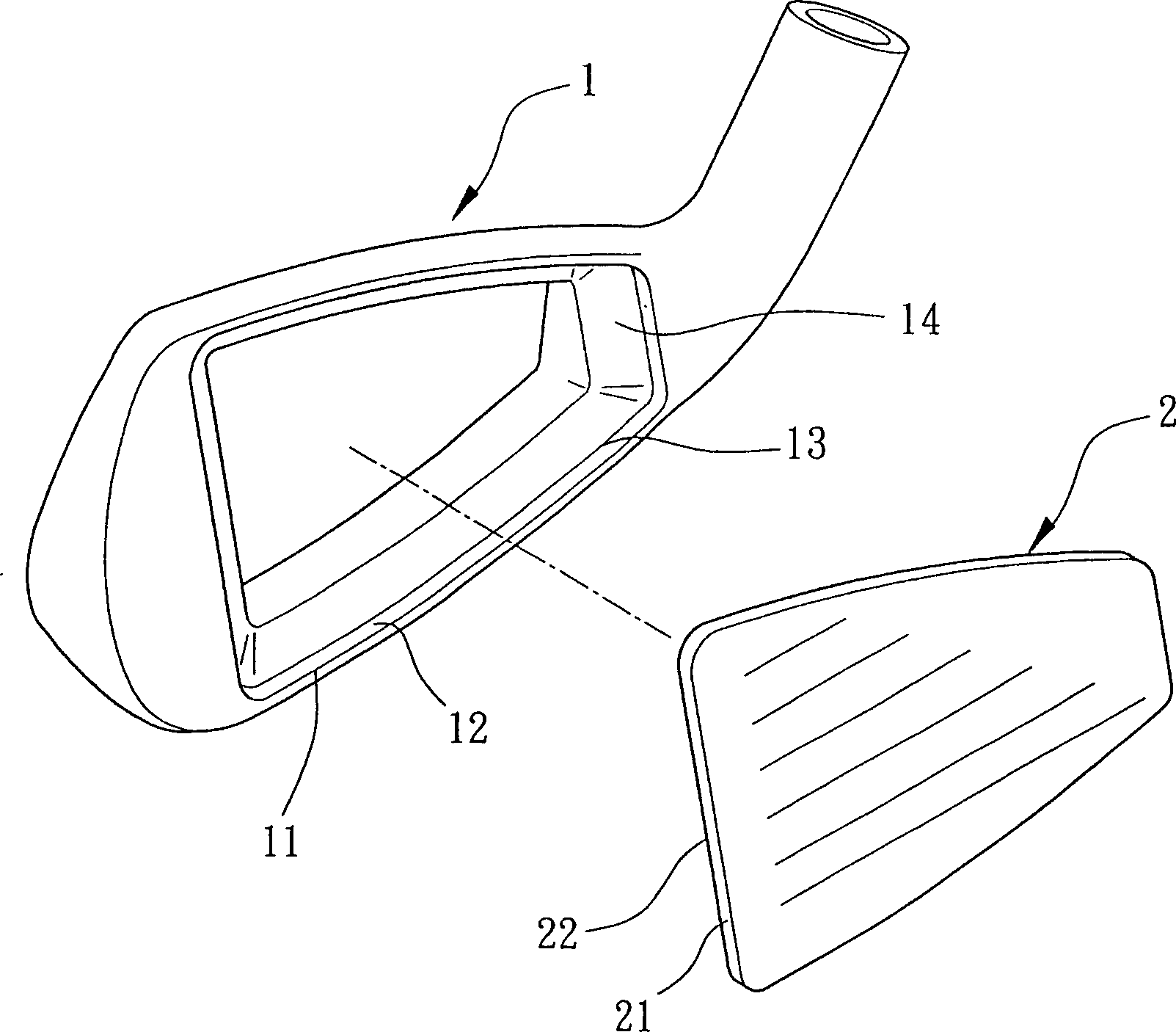
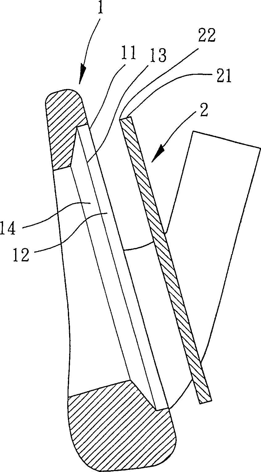
[0032] Such as figure 1 , figure 2 As shown, the present invention includes a club head body 1 and a ball head assembly that is a ball striking panel 2 .

[0033] The club head body 1 is a basic structure selected from existing golf club heads such as iron type, wood type or pusher type. The present invention is an example of an iron type golf club head, but other club head types can also be applied. same concept.

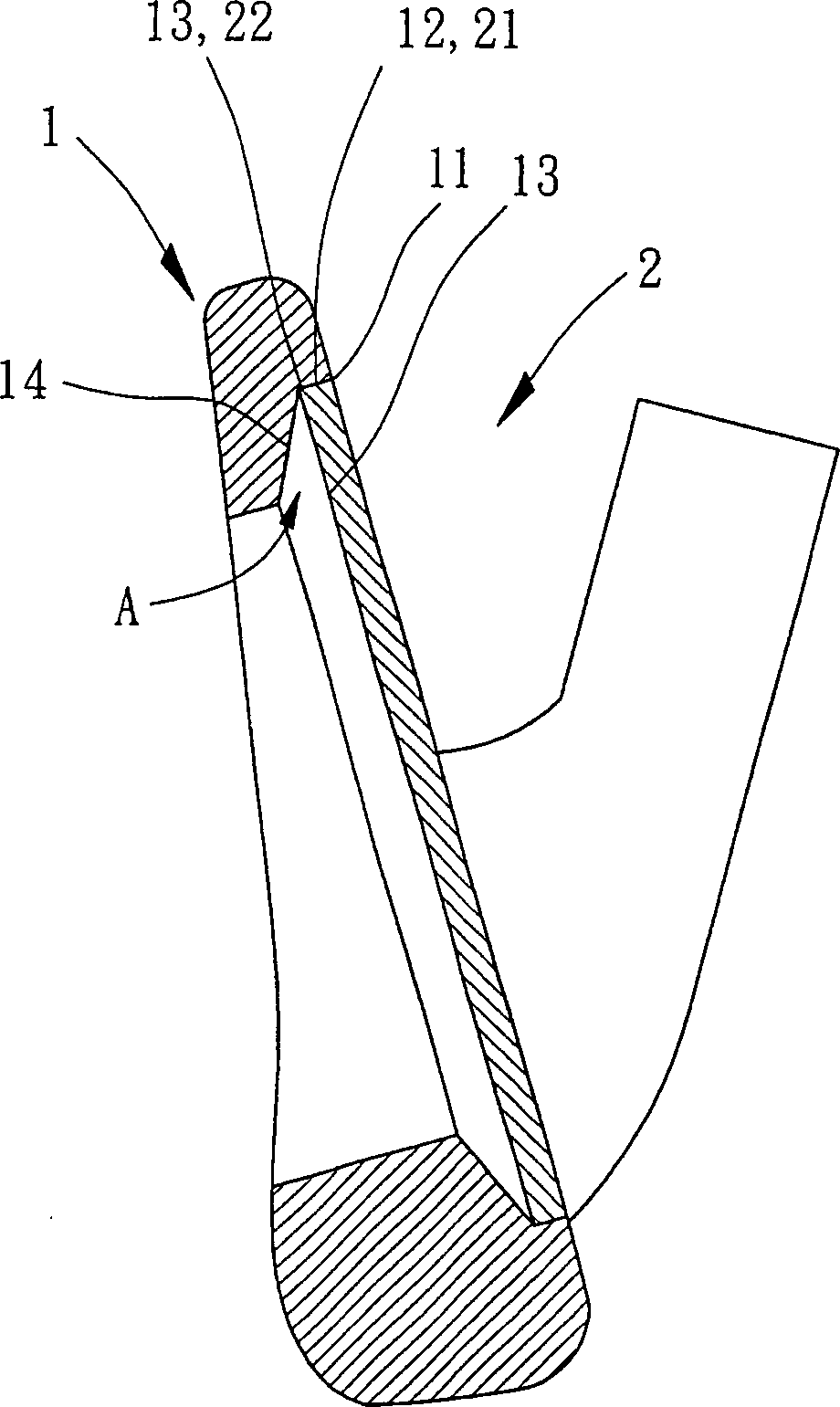
[0034] Such as figure 1 , figure 2 As shown, the club head body 1 is made from materials such as stainless steel, carbon steel, hemp aging steel, tungsten alloy, nickel-based alloy, titanium alloy, etc., and the club head body 1 is further set at an appropriate position, such as the position on the front of the ball. There is an assembly opening 11 , and the assembly opening 11 forms an inner peripheral welding surface 12 , a supporting bottom edge 13 and a diameter-reducing portion 14 in sequence toward the inside of the club head body 1 .

[0035] The inne...


PUM


Abstract

One kind of welded golf club head is disclosed. The welded golf club head has high weld quality, high support strength, high combination reliability and increased elastic deformation tolerance. It includes a club head body and a ball head assembly. The club head body has a assembling opening with successively formed inner weld surface, support bottom edge and reducing part; and the ball head assembly has ring weld surface corresponding to that in the club head body, bottom edge comprising the outer welding surface and back and bottom edge corresponding that in the club head body. One buffering space is formed between the reducing part of the club head body and the back of the ball head assembly.

Description

technical field [0001] The invention belongs to golf equipment components, in particular to a welded golf club head. Background technique [0002] The existing method for combining a golf club head with a ball striking panel includes the following steps: [0003] Manufacture a batting panel with an outer edge and a club head body with a groove seat, the slot seat has an inner edge and a shoulder, the inner edge of the slot seat is provided with a filling flange around the opening periphery of the slot seat; the outer edge of the batting panel and the inner edge of the groove seat of the rod head body is correspondingly inclined outward; [0004] After the ball hitting panel is embedded and positioned on the shoulder of the groove seat of the club head body, at least one pressing block is used to press the filling flange of the club head body, so as to deform the filling flange; [0005] Welding is used to melt and bond the junction of the club head body and the hitting fac...

Claims


Application Information

Patent Timeline
IPC IPC(8): A63B53/04A63B102/32
Inventor 陈建同
Owner FUSHENG IND CO LTD
Learn More