Modulation method, modulation apparatus, demodulation apparatus, and radio communication system
A modulation method and technology for modulating signals, which can be applied to phase-modulated carrier systems, transmission systems, electrical components, etc., and can solve problems such as hindering frequency utilization efficiency
- Summary
- Abstract
- Description
- Claims
- Application Information
AI Technical Summary
Problems solved by technology
Method used
Image

Examples
Embodiment approach 1
[0052] Firstly, the inventive process of the present invention and the principle of the present invention will be explained.
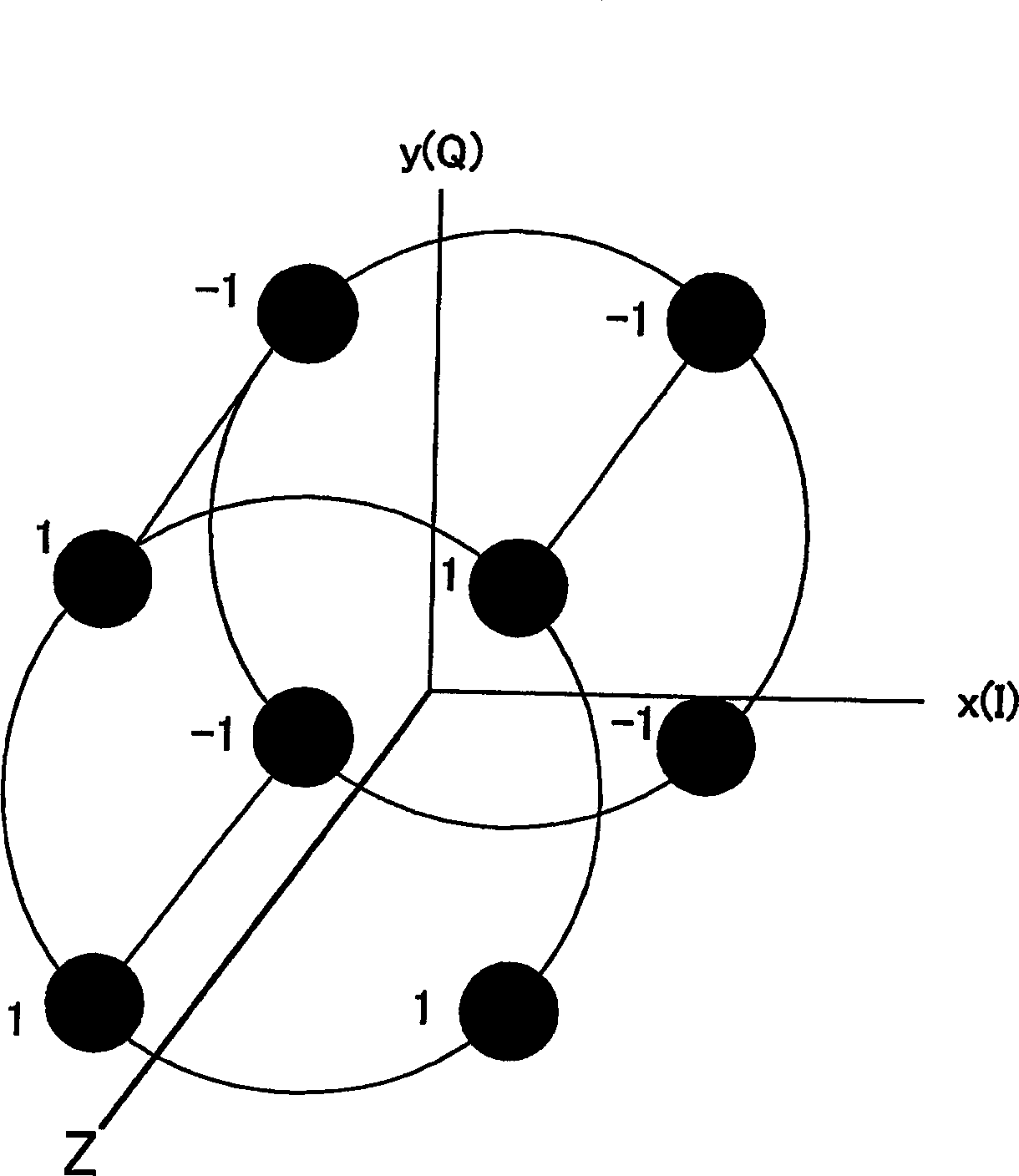
[0053] The inventor of the present invention thinks that if a 4-dimensional space can be constructed on the I-Q plane, the information that can be transmitted in 1 symbol period will become 4 bits (during QPSK), and the frequency efficiency will be doubled.
[0054] However, it is not possible to place multiple QPSK rings on the I-Q plane, so as image 3 As shown, at least a third axis must be added to make it orthogonal on the I-Q plane. This necessity is self-evident. But what kind of physical quantities are used to make the new axes? In the present invention, the third axis (z axis) is considered as the phase dimension.
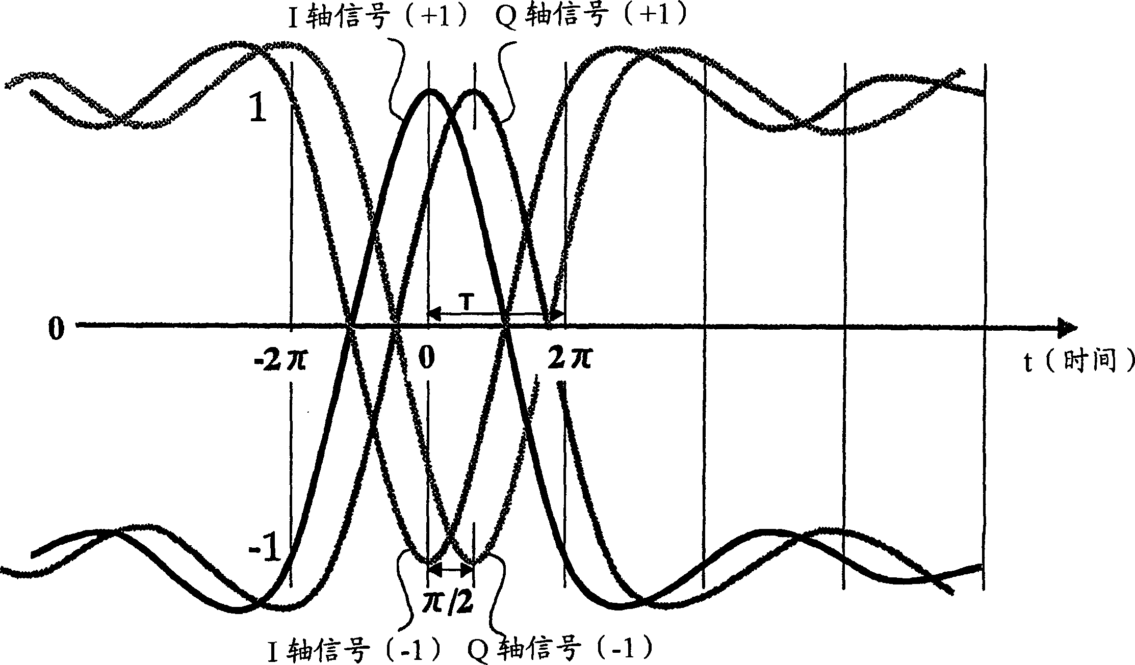
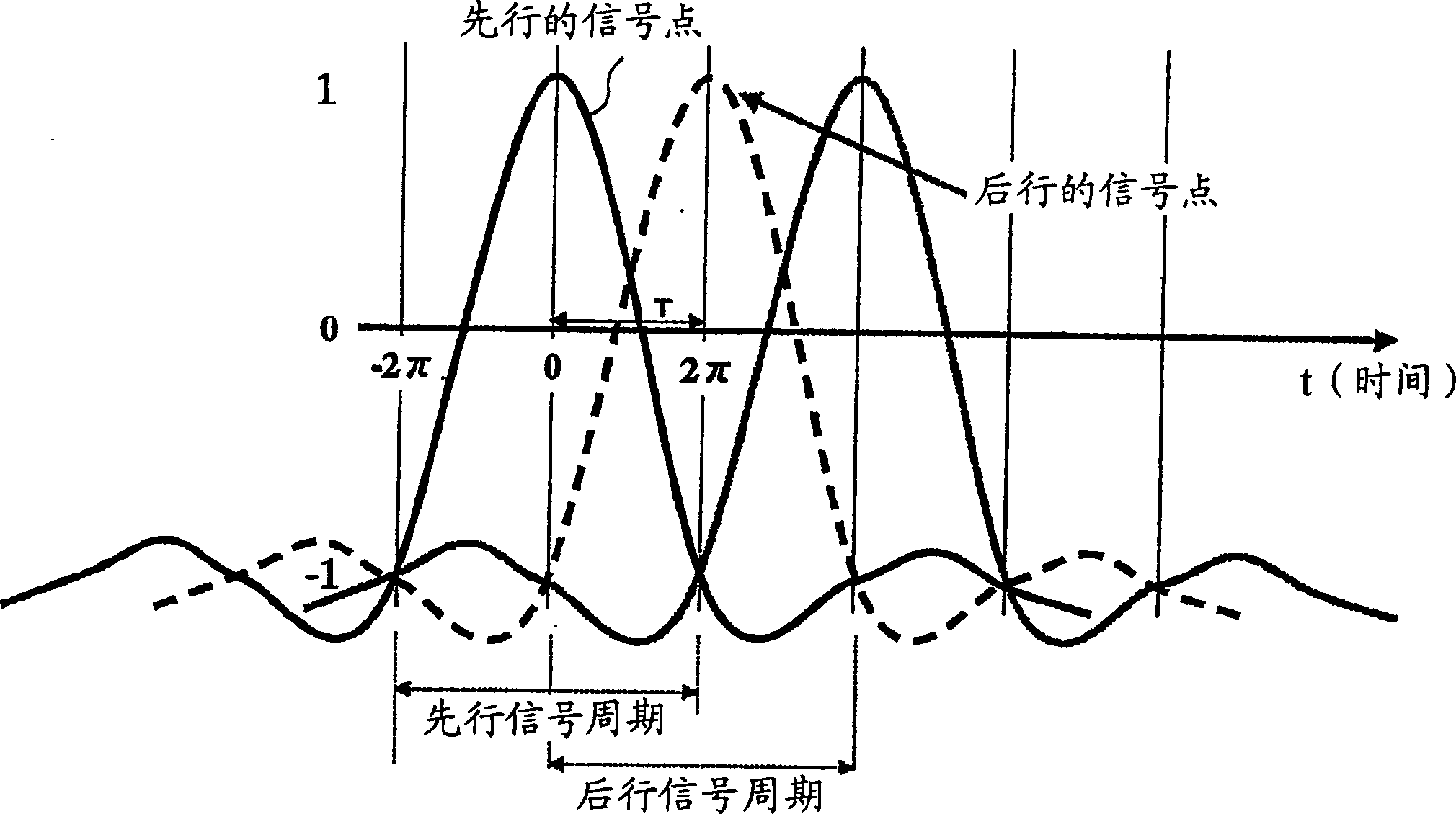
[0055] Here, accommodating two QPSK rings in one symbol period means that two Nyquist waves are arranged on the I-axis, as Figure 4 as shown. The Nyquist wave constitutes its main part within 2 symbol periods, and its orthogon...
Embodiment approach 2
[0088] In Embodiment 1 described above, the amount of information that can be transmitted in one symbol period is 4 bits, which is equivalent to conventional 16QAM. On the other hand, among the conventional modulation schemes, there is a multi-value scheme such as 64QAM for practical purposes. In this embodiment, the efficiency is further improved by the modulation method, and a method corresponding to the conventional multi-value conversion is proposed.
[0089] Figure 18 It is a configuration diagram of a modulation device according to Embodiment 2 of the present invention. exist Figure 18 in, with Figure 12 The same symbol is used in the corresponding part, and the description of this part is omitted. The modulation device 300 inputs the transmission data (TXData) into the mapping processing unit 301, and the mapping processing of the mapping processing unit 301 mainly performs parallelization processing and error correction coding on the transmission data (TXData). ...
Embodiment approach 3
[0095] exist Figure 12 shown in Embodiment 1 and Figure 18 In Embodiment 2 shown, the transmission data that is a parallel signal is arranged in symbols at phase points that are equally divided into four in the symbol interval, that is, at phase zero, phase π / 2, phase π, After the position of the phase 3π / 2 is placed, the quadrature modulation of the symbols of phase zero and phase π is carried out by one modulation, and the quadrature modulation of the symbols of phase π / 2 and phase 3π / 2 is carried out at the same time, that is, the Primary modulation of a symbol signal with a phase difference π (that is, a delay difference of 1 / 2 of the symbol period).
[0096] As a result, the receiver performs quadrature demodulation with a phase difference of π / 2 in the first stage, but the quadrature demodulation in an environment with severe dynamic changes may increase the error between phases compared with the demodulation with a phase difference of π. Intersymbol interference and...
PUM
 Abstract
Description
Claims
Application Information
 - R&D
- Intellectual Property
- Life Sciences
- Materials
- Tech Scout
- Unparalleled Data Quality
- Higher Quality Content
- 60% Fewer Hallucinations
Browse by: Latest US Patents, China's latest patents, Technical Efficacy Thesaurus, Application Domain, Technology Topic, Popular Technical Reports.
© 2025 PatSnap. All rights reserved.Legal|Privacy policy|Modern Slavery Act Transparency Statement|Sitemap|About US| Contact US: help@patsnap.com