
Laser impulse amplification system

A technology for amplifying systems and laser pulses, applied in lasers, laser parts, phonon exciters, etc., can solve the problems of bulky systems, failure of laser oscillators, high costs, etc., and achieve high system reliability and reliability. Improved, low-cost effects

Inactive Publication Date: 2006-07-12
CHINA KEHAN LASER FUJIAN
View PDF0 Cites 5 Cited by
  • Summary
  • Abstract
  • Description
  • Claims
  • Application Information

AI Technical Summary

Problems solved by technology

However, in the laser system, there are many mechanisms that will cause the consumption of the number of reversed particles on the energy level of the working material, thereby reducing the gain of the laser amplifier, and even affecting the stability of the laser system, causing the laser oscillator to die.
The main reasons are 1. The inter-stage coupling of the laser amplifier will form self-excited oscillation or amplified super-radiation phenomenon, which not only reduces the gain of the amplifier, but also self-excited oscillation will feed back to the oscillator, which will affect the stability of the laser oscillator sex
2. For a pulsed laser oscillator, if the noise at the bottom of the pulse leading edge is relatively large, when the signal light passes through the amplifier, the noise at the bottom before the leading edge will be amplified, consuming the number of inversion particles on the energy level of the working substance of the amplifier, so that when The gain of the amplifier decreases when the pulse signal light arrives
Especially when using high-gain multi-stage amplification, the noise can be amplified enough to exhaust the reverse particle number of the working substance
3. There are also other mechanisms such as amplifying spontaneous emission that can also consume the number of inversion particles at the upper energy level
[0004] 1. There are many devices that need to be used, which will easily cause the system to be bulky and need to be adjusted carefully
[0005] 2. Although the use of Faraday optical isolators can effectively prevent the coupling between stages, it cannot eliminate the noise at the bottom of the signal, and the method of electro-optical isolation must still be used to eliminate
[0006] 3. Although the electro-optical isolation method can prevent the coupling between stages and eliminate the noise at the bottom of the pulse, but in order to effectively eliminate the noise, it must be equipped with a fast, low-shaking high-voltage pulse controller. This high-voltage pulse controller technology is complex and costly

Method used


Image

  • Laser impulse amplification system

Examples


Embodiment Construction

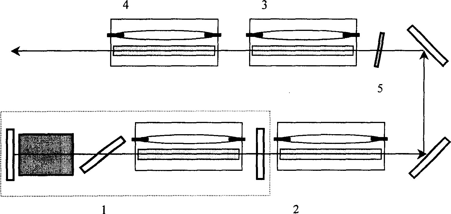
[0021] Referring to the accompanying drawings, it is a preferred embodiment of the present invention when a Q-switched laser oscillator 1 and a three-stage amplifier are used, and a saturable absorber 5 is inserted between the first-stage amplifier 2 and the second-stage amplifier 3 . Since the weak optical signal in front of the Q-switched laser main pulse is not very strong, it is not significantly enhanced when passing through the first-stage amplifier 2; while the spontaneous emission optical signals of the second-stage amplifier 3 and the third-stage amplifier 4, If there is no coupling with the first-stage amplifier 2, no effective amplification will be obtained. Therefore, placing the saturable absorber 5 between the first-stage amplifier 2 and the second-stage amplifier 3 can completely eliminate the interstage coupling between the amplifiers and eliminate the weak light in front of the Q-switched laser pulse signal, making the Q-switched Laser pulses are effectively a...


PUM


Abstract

The invention relates to large-energy laser impulse amplification system with saturated absorption body, which comprises a laser oscillator, an amplifier, and said body on light path between oscillator and amplifier with opposite wave length as laser. This invention overcomes the problem that system has huge volume and can not prevent interstage couple and eliminate impulse bottom noise synchronously.

Description

1. Technical field [0001] The invention relates to a laser pulse amplification system, in particular to a high-energy laser pulse amplification system using a saturable absorber. 2. Background technology [0002] In some laser applications, high-energy laser pulses are often required, and it is generally difficult to obtain high-energy pulse lasers only by laser oscillators. In order to obtain high-energy laser pulses with excellent performance, laser amplification technology is the best way. Both laser amplifiers and laser oscillators are based on the physical process of light amplification by stimulated radiation. The working substance of the laser amplifier is in the particle population inversion state under pumping. When the optical pulse signal generated from the laser oscillator passes through the laser amplifier, since the wavelength of the incident light coincides with the gain spectrum line of the amplifying medium, the inversion of the upper energy level The numb...

Claims


Application Information

Patent Timeline
Patent Type & Authority Applications(China)
IPC IPC(8): H01S3/00
Inventor 朱少岚王屹山赵卫朱宝亮刘莉
Owner CHINA KEHAN LASER FUJIAN
Learn More