Flat tube for aluminium heat exchanger

A heat exchanger and flat tube technology, applied in the field of aluminum flat tubes, can solve problems such as corrosion of contact parts, and achieve the effect of high reliability

Inactive Publication Date: 2006-06-07
T RAD CO LTD
View PDF0 Cites 7 Cited by
  • Summary
  • Abstract
  • Description
  • Claims
  • Application Information

AI Technical Summary

Problems solved by technology

However, when the partition 7 is welded by brazing filler metal on the outside of the tube, both edge portions in the width direction of the strip material are turned inward, and then, it is found that when the brazing filler metal is melted, as Figure 10 As shown, the solder 3 is held on the folded top surface, the retained solder is then in contact with the sacrificial anode material, and corrosion is likely to occur at this contact portion

Method used


Image

  • Flat tube for aluminium heat exchanger
  • Flat tube for aluminium heat exchanger
  • Flat tube for aluminium heat exchanger

Examples


Embodiment Construction

[0032] Embodiments of the present invention are described as follows with reference to the accompanying drawings:

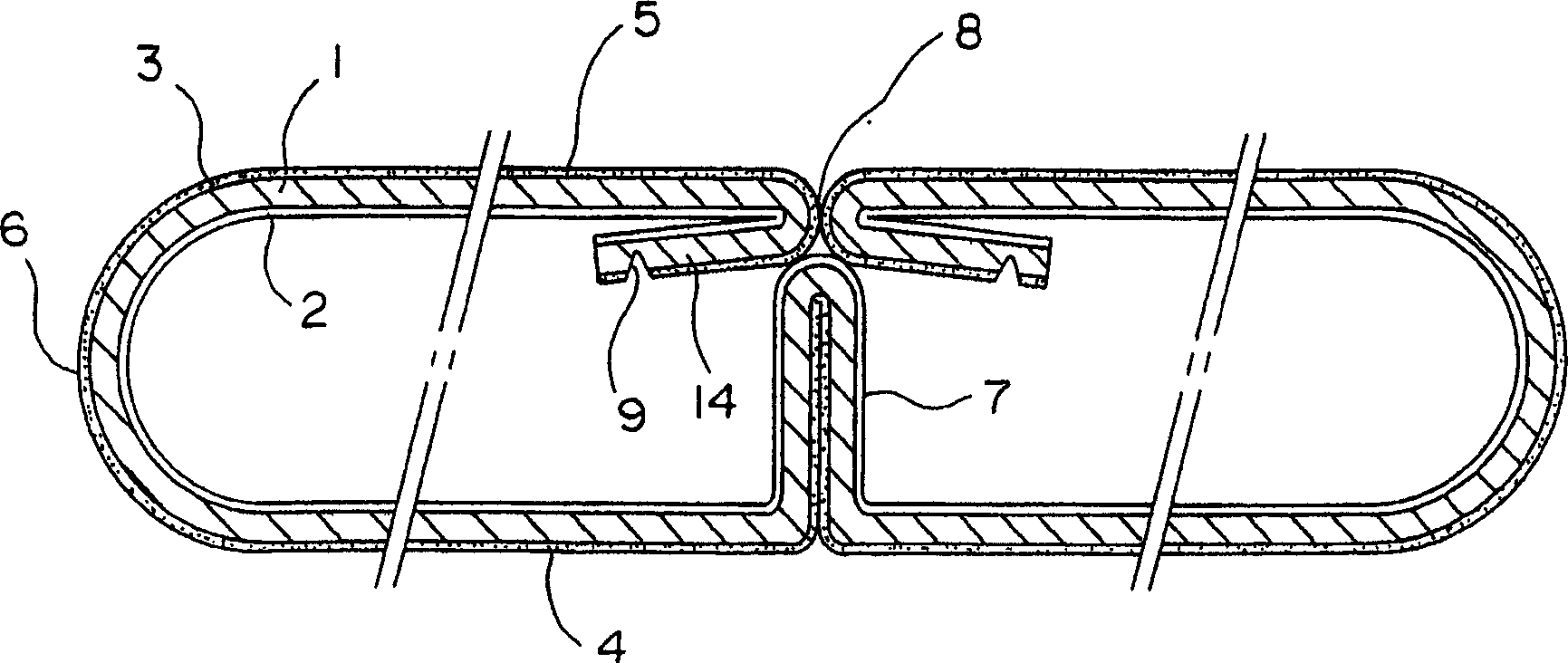
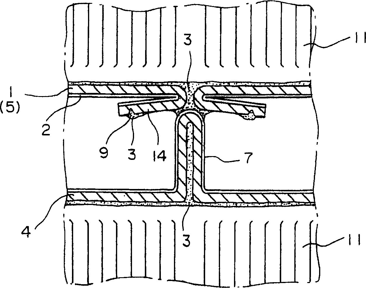
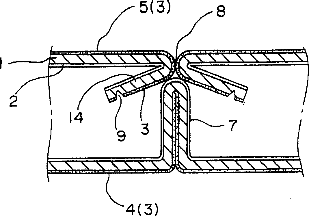
[0033] figure 1 A cross-sectional view of a flat tube according to a first embodiment of the invention is shown, given the state before welding. figure 2 A cross-sectional view of the main part of the flat tube is shown, giving the state after welding.

[0034] The first embodiment presents a flat tube formed by bending in its width direction an aluminum strip material made of brazing filler metal 3 coated with an aluminum alloy on its outer surface and It consists of an aluminum core material 1 coated with a sacrificial anode material 2 made of aluminum alloy on its inner surface.

[0035]The strip-shaped material is bent in the width direction so that the first flat surface 4 and the second flat surface 5 face each other in parallel, while the first flat surface 4 and the second flat surface are connected in the width direction by a pair of bent portions 6 ...


PUM


Abstract

An aluminum flat tube for a heat exchanger made of an aluminum strip material coated on its inner surface to form a flat cross-section close to a B-shape by bending in the width direction. It consists of a core material (1) coated with brazing material (3) on its outer surface by sacrificial anode material (2). In order to improve the corrosion resistance of the inner surface of the tube, both edge portions in the width direction of the strip material are bent inward into the tube so that the front end edges of the edge portions are separated from the flat inner surface of the tube.

Description

technical field [0001] The invention relates to an aluminum flat tube for a heat exchanger, which has a B-shaped curved cross-section and is coated on its outer surface with solder. Background technique [0002] Such as Figure 9 As shown, the aluminum flat tube for the heat exchanger has a flat and nearly B-shaped cross-section, wherein the partition 7 stands upright at the center in the width direction and includes a top connected with a joint part 8 through which It is formed by folding the two edge portions of the strip-shaped material. At the joint portion 8 , the two edge portions of the strip material are folded over 180°, exposing their respective solder 3 on the inside, said solder 3 being in contact with the top of the partition 7 . [0003] Such as Figure 10 As shown, the thus formed flat tube is put into a high temperature furnace where the brazing filler metal 3 is melted and then cooled to solidify, and the brazing filler metal 3 can weld the top of the part...

Claims


Application Information

Patent Timeline
Patent Type & Authority Applications(China)
IPC IPC(8): F28F1/02B23K1/14B23K101/06B23K101/14F28D1/03F28F19/06
CPCF28D1/0391
Inventor 伊神多加司村山匠
Owner T RAD CO LTD
Why Eureka
Try Eureka