Flexible printed circuit board apposition method and guide pin
A flexible printing and circuit board technology, applied in the direction of printed circuit, printed circuit manufacturing, electrical components, etc., can solve the problems of complex structure and poor operation, and achieve a good guiding effect
- Summary
- Abstract
- Description
- Claims
- Application Information
AI Technical Summary
Problems solved by technology
Method used
Image
Examples
Embodiment 1
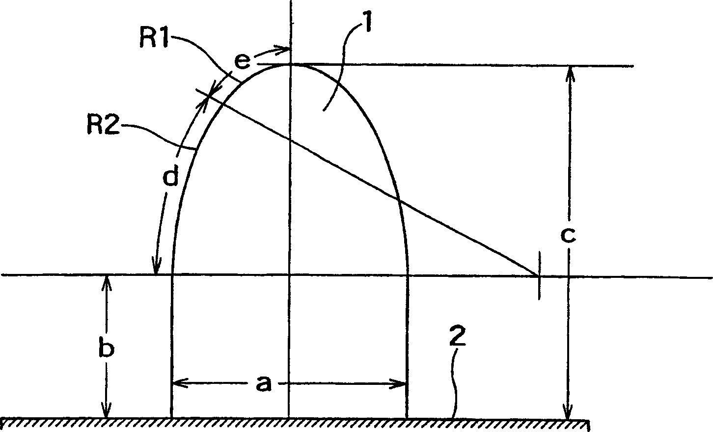
[0026] figure 1 Shown is the side view shape of the guide pin used in the method of the present invention, ie the guide pin of the present invention. The guide pin 1 is fixed on the lower clamp 2, its overall length, that is, its height, is 3.0-4.0 mm, and its top end is rounded. Furthermore, the base end portion has a diameter corresponding to the predetermined alignment accuracy, and its continuous diameter length is 0.5 to 1.2 mm, and the diameter of the tip portion is continuously tapered from the upper portion of the base end portion with two-stage curvature. As for the curvature to narrow the diameter of the tip, the radius of curvature R2 of the portion d near the base end is 4.0 to 4.5 mm, and the radius of curvature R1 of the tip portion e is 0.5 to 1.1 mm.
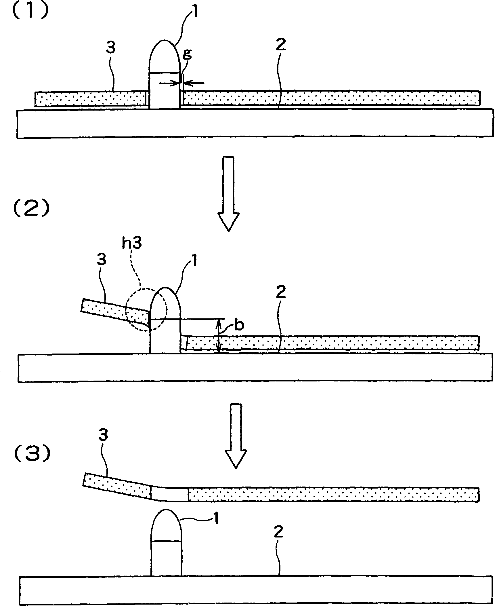
[0027] figure 2 Shown is figure 1 The effect of the shown guide pin, it represents the state that the flexible printed circuit board 3 is arranged on the lower side fixture 2 [ figure 2 (1)] Start to slow...
PUM
 Abstract
Description
Claims
Application Information
 - R&D
- Intellectual Property
- Life Sciences
- Materials
- Tech Scout
- Unparalleled Data Quality
- Higher Quality Content
- 60% Fewer Hallucinations
Browse by: Latest US Patents, China's latest patents, Technical Efficacy Thesaurus, Application Domain, Technology Topic, Popular Technical Reports.
© 2025 PatSnap. All rights reserved.Legal|Privacy policy|Modern Slavery Act Transparency Statement|Sitemap|About US| Contact US: help@patsnap.com


