
Distributed covering network

An overlay network and distributed technology, applied in the field of distributed overlay network, can solve the problem of large delay between uplink and downlink data, and achieve the effect of high security and improved safety factor.

Inactive Publication Date: 2006-05-31
HUAWEI TECH CO LTD
View PDF0 Cites 3 Cited by
  • Summary
  • Abstract
  • Description
  • Claims
  • Application Information

AI Technical Summary

Problems solved by technology

[0006] The present invention provides a distributed coverage network to solve the technical problem in the prior art that there is a large time delay difference between the uplink and downlink data transmitted between the RRU and the master station of the base station

Method used

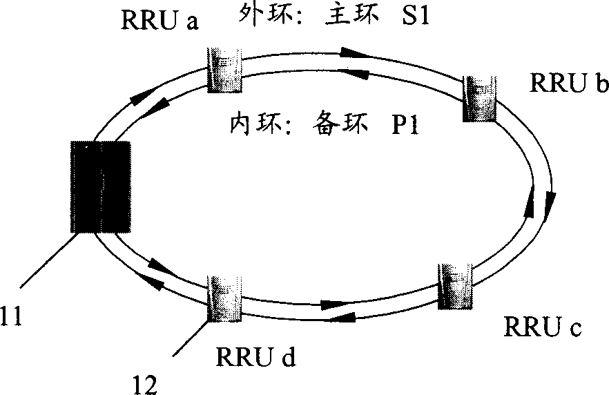

Image

  • Distributed covering network
  • Distributed covering network
  • Distributed covering network

Examples


Embodiment Construction

[0014] The present invention will be described in detail below in conjunction with the accompanying drawings.

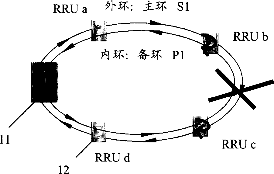
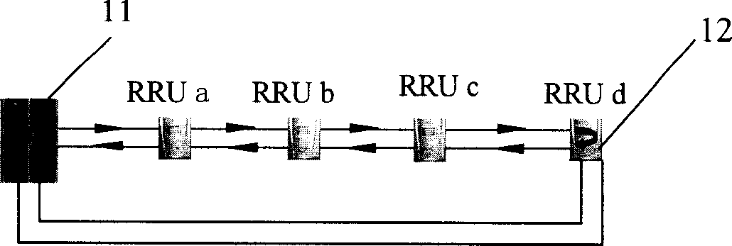
[0015] see Figure 2A , which is a structural schematic diagram of a distributed coverage network of the present invention, the distributed coverage network includes a base station main station 11 and a number of radio frequency remote modules 12, each radio frequency remote module 12 is connected to an antenna (not drawn in the figure As shown), the base station main station 11 and several radio frequency remote units (RRU) 12 are cascaded sequentially through optical fibers, and the last level of radio frequency remote units are directly connected to the base station main station 11 through optical fibers.

[0016] In order to enable each RRU to obtain its own data from the downlink data delivered by the master station 11 of the base station, the downlink data is divided into several time slots in advance, and each RRU has a corresponding time slot. When the base ...


PUM


Abstract

The invention consists of a host base station and several radio frequency-far end modules. Each radio frequency far end module connects to antenna. Several radiofrequency far end modules are concatenated one-by-one through optical fiber in turn, and the one of radio frequency far end module in last stage connects to the host base station. The invention makes the up stream and down stream data transmitted between RRU and host base station have same time delay. The data transmitted in the distributing overlay network has high security level, and when the break point appears in transmission link, the RRU behind the break point is connected with host base station through redundant optical fiber by new chain type network.

Description

technical field [0001] The invention relates to the communication field, and is especially applicable to the distributed coverage network of the 3G system (the third generation wireless communication system). Background technique [0002] During the development of 3G networks, with the increase of the number of users, the demand for network capacity also increases. For this reason, mobile operators usually consider building or renting new computer rooms to achieve the purpose of adding base stations. However, building or renting a new computer room will cost a lot of money. [0003] In order to improve the system coverage performance while saving the computer room of the mobile operator, the prior art discloses a distributed coverage network. The distributed coverage network is to centrally place large-capacity base station main stations in the operator's computer room, and the antennas are respectively set on the sites determined by the network planning through RRU (Remot...

Claims


Application Information

Patent Timeline
Patent Type & Authority Applications(China)
IPC IPC(8): H04W16/18H04B10/20H04B10/2575H04L12/28
Inventor 胡强
Owner HUAWEI TECH CO LTD
Learn More