Electric toothbrush

An electric toothbrush and toothbrush technology, applied in dentistry, tooth cleaning, medical science, etc., can solve problems such as expensive, unreliable, and complex structure of the brush head

Inactive Publication Date: 2006-05-31
吴旭榕
View PDF0 Cites 8 Cited by
  • Summary
  • Abstract
  • Description
  • Claims
  • Application Information

AI Technical Summary

Problems solved by technology

The drive mechanism driven by the electric motor in the above-mentioned brush handle is well known and widely used. In the known art, there are various mechanical linkages including gears, which are used to convert the rotary motion of the electric motor into pressing the brush head. The swing or other movement methods, but these machine devices are complex in structure and not very reliable, especially a special toothbrush with complex structure must be used. The internal structure of the head and brush head is complicated and expensive

Method used


Image

  • Electric toothbrush
  • Electric toothbrush
  • Electric toothbrush

Examples


Embodiment Construction

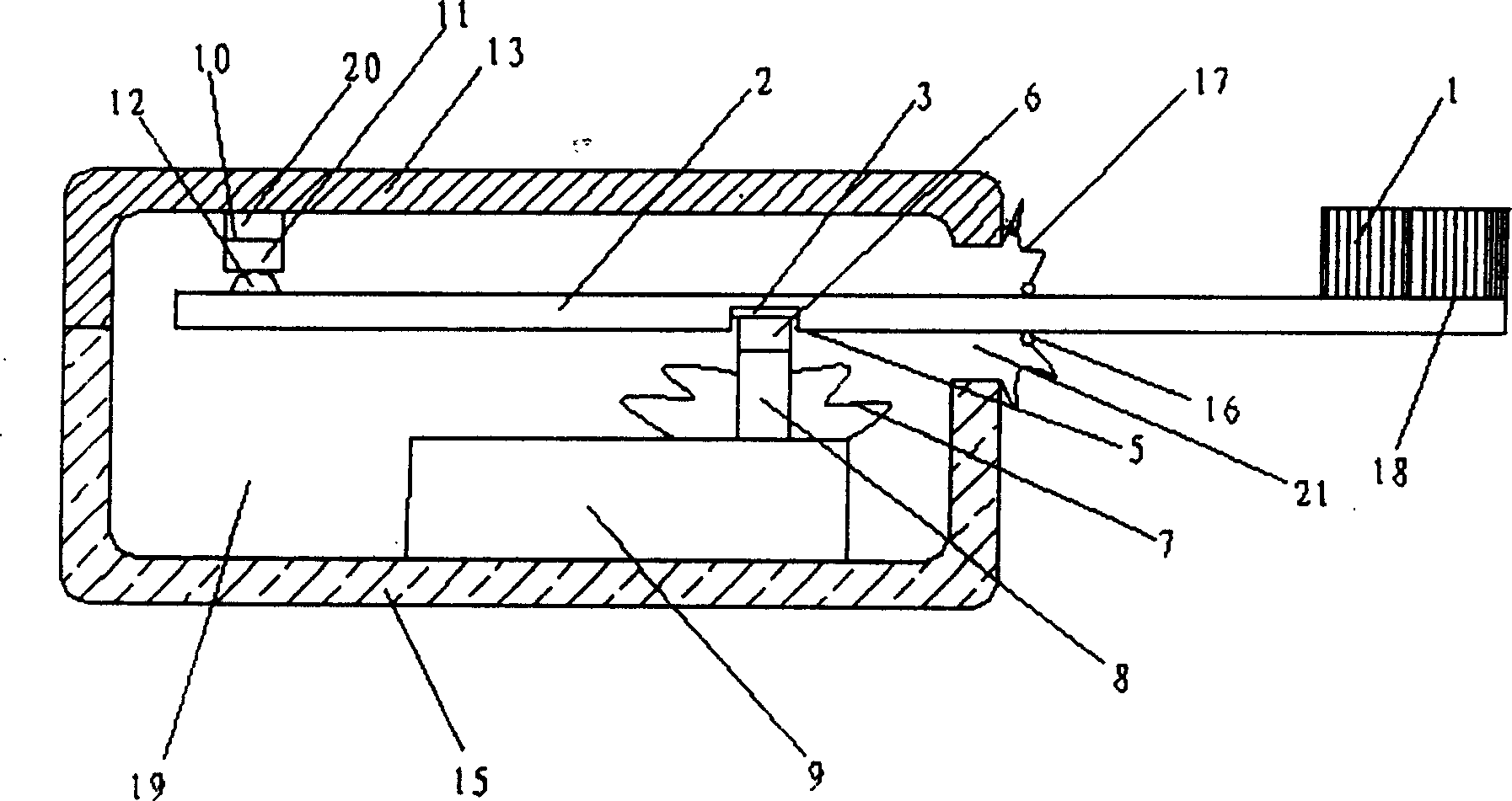
[0030] Such as figure 1 As shown, figure 1 It is a transverse cross-sectional view of the first embodiment of the present invention. The electric toothbrush is composed of an electric motor 19 and a toothbrush 18. The toothbrush 18 is composed of bristles 1 at the end and a handle 2. The bristles 1 are fixed to one end of the handle 2, and the electric motor is driven by an electric drive mechanism 9. The swing mechanism is composed of a swing link 6 and a support assembly 10. The swing link 6 is connected to the output end 8 of the swing shaft of the electric drive mechanism and can be connected to the swing shaft of the electric drive mechanism 9 The output end 8 is driven to swing back and forth, and the brush handle 2 is connected to the swing connector 6 to swing back and forth around the support assembly 10 under the drive of the output end 8 of the swing shaft. The above-mentioned swing connector 6 is a magnetic block 6. The above-mentioned magnetic block 6 is connected a...


PUM


Abstract

An electric tooth-brush is composed of an electric driver and a tooth-brush consisting of brush head and handle. Said electric driver consists of electric drive mechanism and swinging mechanism which is composed of swinging connection part and supporter assemblage. Under the action of electric driver, the handle linked with said swinging connection part magnetically can swing back and forth.

Description

Technical field [0001] The invention relates to an electric toothbrush. Background technique [0002] Many electric toothbrushes have been developed for many years in the U.S. S. Patent Nos. 5,070,567, 5,186,627, 5,274,870, 5,341,534, 5,378,153, 5,732,433 disclose these devices. The existing electric toothbrush is composed of a brush head, a brush handle and a drive mechanism in the brush handle driven by a motor. The drive mechanism driven by the motor in the brush handle is well-known and widely used. In the known technology, there are various mechanical and mechanical connection devices including gears, which are used to convert the rotational movement of the motor into a brush head. However, these machines have complex structures and are not very reliable. Especially, special toothbrushes with complex structures must be used. The internal structure of the head brush head is complex and expensive. Summary of the invention [0003] The purpose of the present invention is to ov...

Claims


Application Information

Patent Timeline
Patent Type & Authority Applications(China)
IPC IPC(8): A61C17/34
Inventor 吴旭榕
Owner 吴旭榕
Why Eureka
Try Eureka